Raceway SolutionsTM
Conventional Underfloor Duct
In-Floor Wire Management Systems
Casino Duct Flush Activation Duct Trench Duct Wall Duct
Raceway Solutions In-floor Wire Management Systems
Applications
- •
- Commercial Buildings
- •
- Retail Facilities
- •
- Office Buildings
- •
- Casinos
- Schools and Universities
- Medical Facilities including X-Ray and MRI Rooms
Features and Benefits
- Five Labor Saving Designs
- Systems include a complete line of accessories and fittings for design flexibility
- Unique one-piece multi-compartment duct reduces installation labor
- Package and ship by room, area, or floor
- Custom sizes available
Raceway SolutionsTM
Conventional Underfloor Duct Pgs. 2-11
Raceway SolutionsTM
Flush Activation Duct Pgs. 12-18
Raceway SolutionsTM
Casino Underfloor Duct Pgs. 19-23
Raceway SolutionsTM
Trench Duct Pgs. 24-34
Raceway SolutionsTM
Wall Duct Pgs. 35-45
The Power of Intelligent Design
Raceway Solutions Underfloor Duct Systems offer maximum flexibility in designing or building in-slab raceway systems for distribution of power, voice and data conductors. Our Conventional, Casino, Flush Activation, Trench Underfloor, and Wall Duct Systems provide a range of distinct benefits, depending on chosen application. There are many potential uses for the wide variety of products shown in this catalog. Your local representative will assist you in selecting the appropriate combination of systems for your project and provide any additional information required to help you complete your job.

Raceway SolutionsTM
Conventional Underfloor Duct
Multi-Compartment Conventional Duct Saves Time and Money in Your In-Slab Wire Management System
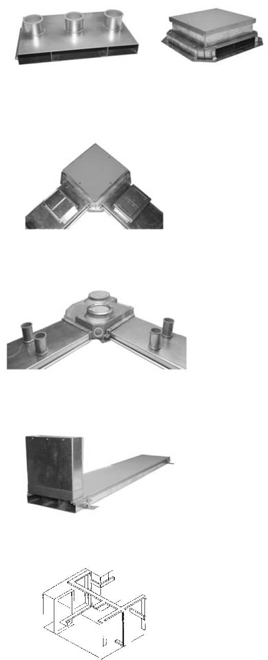
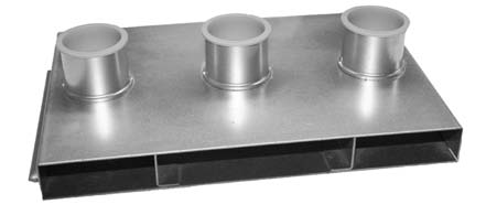
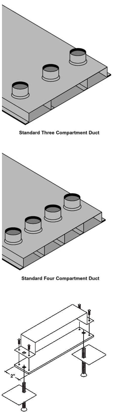
The Raceway Solutions Conventional Underfloor Duct System is an in-slab wire management product for delivering power, voice and data services to numerous point of sale locations or office workstations. The Raceway Solutions Conventional Underfloor Duct System is uniquely designed with multiple compartments, allowing unlimited design options and fantastic cost savings in labor and materials from other single-compartment systems.
Here is how Raceway Solutions Conventional Underfloor Duct works for you:
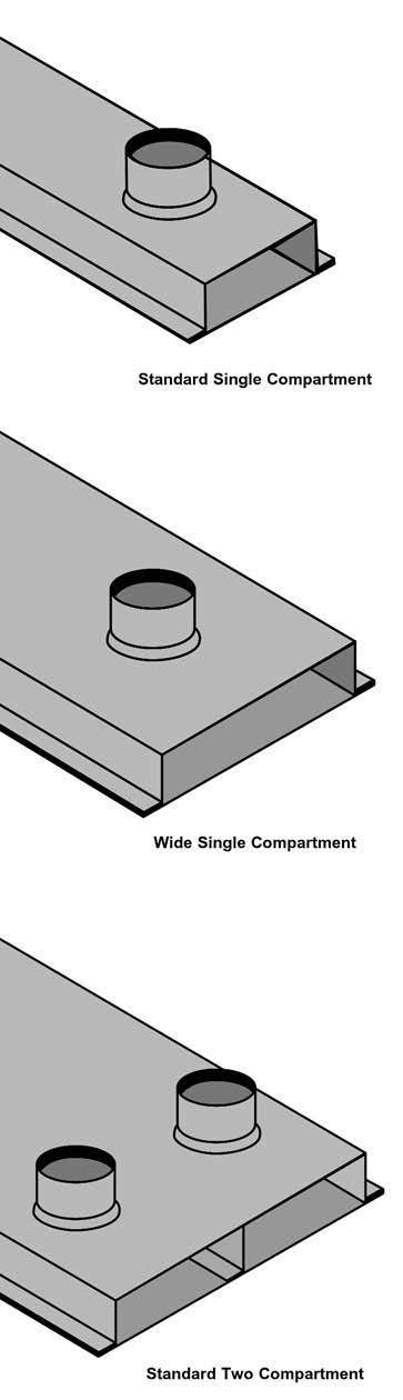
- Five designs available, providing the most complete offering in the industry.
- Multi-compartment duct, drastically reducing installation and material costs.
- Four insert heights, expanding the design options of 1", 1½", 2" and 3" sizes.
- Inclusive tile trim in the junction box, providing the installer the on-site option of using the trim or leaving it recessed.
- Combination duct couplers and supports, reducing material and labor costs using the same part for two functions.
- Meets or exceeds UL 884 specifications, assuring a fully approved system
from one manufacturer. Matched with our strong national distribution and complete technical and applications support, the Raceway Solutions Conventional Underfloor Duct system is the perfect solution for your underfloor wire management needs, and at an affordable price. As a part of our complete wire management and components offering, Raceway Solutions Conventional Underfloor Duct is perfect for:
| • Supermarkets | • Office Buildings |
| • Retail Facilities | • Airports |
| • Casinos | • Institutional Facilities |

| 203 | - | 2 | - | 12 |
|---|---|---|---|---|
| # of Cells 1 = Single Cell 2 = Two Cell 3 = Three Cell 4 = Four Cell | Insert Height B = Blank 1 = 1” Height 15 = 1½” Height 2 = 2” Height 3 = 3” Height | Insert Spacing 12 & 24 Standard 6, 18, & 36 (optional) | ||

Raceway SolutionsTM
Conventional Underfloor Duct
| Cat.No. | Duct Width | Duct Depth | Insert Spacing |
|---|---|---|---|
| 201-B | ¼" | 1½" | No Inserts |
| 201-3-24 | ¼" | 1½" | 3" High Inserts 24"o.c. |
| 201-2-24 | 3¼" | 1½" | 2" High Inserts 24"o.c. |
| 201-15-24 | 3¼" | 1½" | 1½" High Inserts 24" o.c. |
| 201-1-24 | 3¼" | 1½" | 1" High Inserts 24" o.c. |
| 201-3-12 | 3¼" | 1½" | 3" High Inserts 12" o.c. |
| 201-2-12 | 3¼" | 1½" | 2" High Inserts 12" o.c. |
| 201-15-12 | 3¼" | 1½" | 1½" High Inserts 12" o.c. |
| 201-1-12 | 3¼" | 1½" | 1" High Inserts 12" o.c. |
Material: 14 gauge pre-galvanized steel with 668 coating Presets: Die-cast zinc UL Listing No.884
| Cat.No. | Duct Width | Duct Depth | Insert Spacing |
| 201W-B | 5⅞" | 1½" | No Inserts |
| 201W-3-24 | 5⅞" | 1½" | 3" High Inserts 24" o.c. |
| 201W-2-24 | 5⅞" | 1½" | 2" High Inserts 24" o.c. |
| 201W-15-24 | 5⅞" | 1½" | 1½" High Inserts 24" o.c. |
| 201W-1-24 | 5⅞" | 1½" | 1" High Inserts 24" o.c. |
| 201W-3-12 | 5⅞" | 1½" | 3" High Inserts 12" o.c. |
| 201W-2-12 | 5⅞" | 1½" | 2" High Inserts 12" o.c. |
| 201W-15-12 | 5⅞" | 1½" | 1½" High Inserts 12" o.c. |
| 201W-1-12 | 5⅞" | 1½" | 1" High Inserts 12" o.c. |
Material: 14 gauge pre-galvanized steel with 668 coating Presets: Die-cast zinc UL Listing No.884
| Cat.No. | Duct Width | Duct Depth | Insert Spacing | Compartment Width |
|---|---|---|---|---|
| 202-B | 10" | 1½" | No Inserts | 2 @ 5" |
| 202-3-24 | 10" | 1½" | 3" High Inserts 24" o.c. | 2 @ 5" |
| 202-2-24 | 10" | 1½" | 2" High Inserts 24" o.c. | 2 @ 5" |
| 202-15-24 | 10" | 1½" | 1½" High Inserts 24" o.c. | 2 @ 5" |
| 202-1-24 | 10" | 1½" | 1" High Inserts 24" o.c. | 2 @ 5" |
| 202-3-12 | 10" | 1½" | 3" High Inserts 12" o.c. | 2 @ 5" |
| 202-2-12 | 10" | 1½" | 2" High Inserts 12" o.c. | 2 @ 5" |
| 202-15-12 | 10" | 1½" | 1½" High Inserts 12" o.c. | 2 @ 5" |
| 202-1-12 | 10" | 1½" | 1" High Inserts 12" o.c. | 2 @ 5" |
Material: 14 gauge pre-galvanized steel with 668 coating Presets: Die-cast zinc UL Listing No.884
For different compartment spacing consult factory.

Raceway SolutionsTM
Conventional Underfloor Duct
| Cat.No. | Duct Width | Duct Depth | Insert Spacing | Compartment Width |
|---|---|---|---|---|
| 203-B | 15" | 1½" | No Inserts | 2 @ 4" – 1 @ 6¾" |
| 203-3-24 | 15" | 1½" | 3" High Inserts 24" o.c. | 2 @ 4" – 1 @ 6¾" |
| 203-2-24 | 15" | 1½" | 2" High Inserts 24" o.c. | 2 @ 4" – 1 @ 6¾" |
| 203-15-24 | 15" | 1½" | 1½" High Inserts 24" o.c. | 2 @ 4"– 1 @ 6¾" |
| 203-1-24 | 15" | 1½" | 1'' High Inserts 24" o.c. | 2 @ 4"– 1 @ 6¾" |
| 203-3-12 | 15" | 1½" | 3" High Inserts 12" o.c. | 2 @ 4"– 1 @ 6¾" |
| 203-2-12 | 15" | 1½" | 2" High Inserts 12" o.c. | 2 @ 4"– 1 @ 6¾" |
| 203-15-12 | 15" | 1½" | 1½" High Inserts 12" o.c. | 2 @ 4"– 1 @ 6¾" |
| 203-1-12 | 15" | 1½" | 1" High Inserts 12" o.c. | 2 @ 4"– 1 @ 6¾" |
All duct standard 10' lengths. Material: 14 gauge pre-galvanized steel with 668 coating Presets: Die-cast zinc UL Listing No. 884
For different compartment spacing consult factory.
| Cat.No. | Duct Width | Duct Depth | Insert Spacing | Compartment Width |
| 204-B | 15" | 1½" | No Inserts | 4 @ 3⅝" |
| 204-3-24 | 15" | 1½" | 3" High Inserts 24" o.c. | 4 @ 3⅝" |
204-2-24 15" 1½" 2" High Inserts 24" o.c. 4 @ 3⅝" 204-15-24 15" 1½"1½" High Inserts 24" o.c. 4 @ 3⅝"
204-1-24 15" 1½" 1" High Inserts 24" o.c. 4 @ 3⅝" 204-3-12 15" 1½" 3" High Inserts 12" o.c. 4 @ 3⅝"
204-2-12 15" 1½" 2" High Inserts 12" o.c. 4 @ 3⅝" 204-15-12 15" 1½"1½" High Inserts 12" o.c. 4 @ 3⅝"
204-1-12 15" 1½" 1" High Inserts 12" o.c. 4 @ 3⅝"
All duct standard 10' lengths. Material: 14 gauge pre-galvanized steel with 668 coating Presets: Die-cast zinc UL Listing No. 884
Cat.No. Description
| 201-DCS | Standard Single Cell Duct |
|---|---|
| 201W-DCS | Wide Single Cell Duct |
| 202-DCS | Two Cell Duct |
| 203-DCS | Three and Four Cell Duct |
Material: 14 gauge pre-galvanized steel with 668 coating UL Listing No. 668
Raceway Solutions duct coupler/supports provide a means of not only coupling duct sections together but also supporting the duct sections. It is recommended that a support/coupler be used every 5' of duct run.

Raceway SolutionsTM
Conventional Underfloor Duct
| Cat. No. | Description | Inserts |
| 201-JB-4 | For Standard Single Cell Blank Duct | For 4" Afterset Only |
| 201-JB-3 | For Standard Single Cell Blank Duct | For 3" Afterset or Preset |
| 201-JB-2 | For Standard Single Cell Duct | For 2" Preset or Afterset |
| 201-JB-15 | For Standard Single Cell Duct | For 1½" Preset or Afterset |
| 201-JB-1 | For Standard Single Cell Duct | For 1" Preset or Afterset |
| 201W-JB-4 | For Wide Single Cell Blank Duct | For 4" Afterset Only |
| 201W-JB-3 | For Wide Single Cell Blank Duct | For 3" Afterset or Preset |
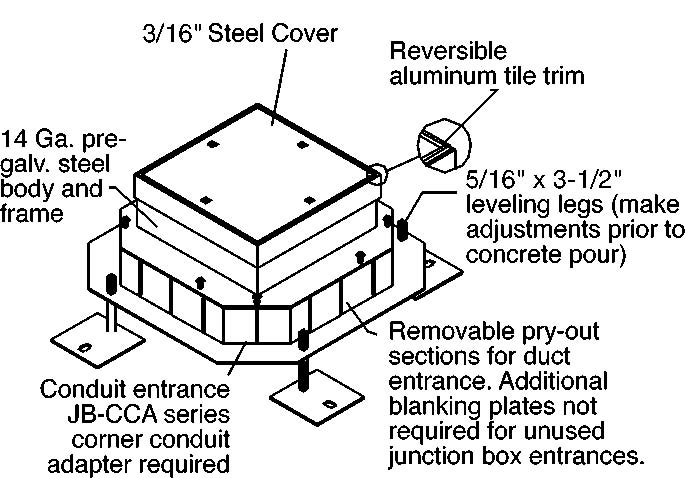
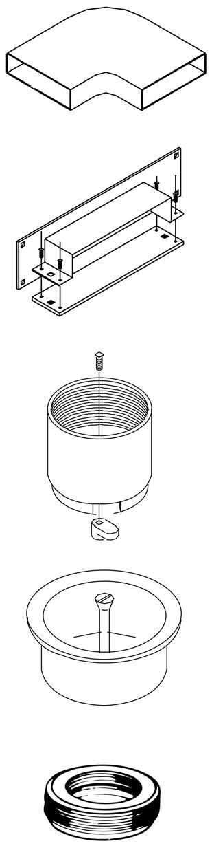
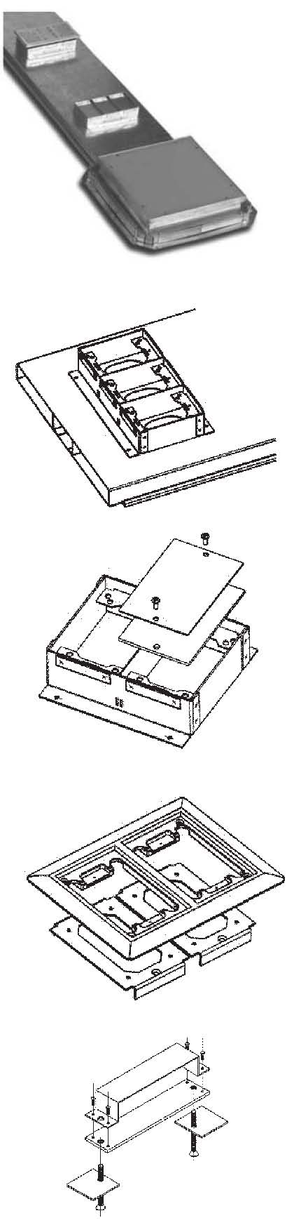
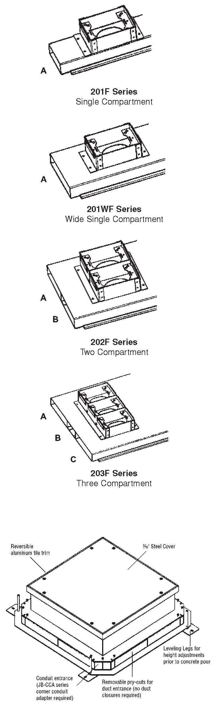
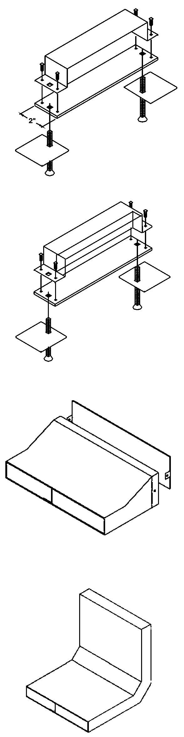
| Raceway Solutions Underfloor Duct Junction Boxes offer several labor saving and design advantages. The boxes are manufactured with a concrete ring approximately ¼" higher than the corresponding duct to allow for the proper amount of concrete fill over the duct inserts. Also, the boxes are made from durable 14 ga. pre-galvanized steel and come with a reinforced 3/16" thick steel cover. In addition, our junction boxes include a built-in tile trim which can be easily removed, flipped over and reinstalled when the surrounding floor tile is installed. Our junction boxes are also manufactured with removable duct and corner entrance plugs which are easily removed for duct and corner conduit adapter entrance. | 201W-JB-2 201W-JB-15 201W-JB-1 202-JB-4 | For Wide Single Cell Duct For Wide Single Cell Duct For Wide Single Cell Duct For Standard Two Cell Blank Duct | For 2" Preset or Afterset For 1½" Preset or Afterset For 1" Preset or Afterset For 4" Afterset Only |
|---|---|---|---|
| 202-JB-3 202-JB-2 202-JB-15 202-JB-1 203-JB-4 203-JB-3 203-JB-2 203-JB-15 | For Standard Two Cell Blank Duct For Standard Two Cell Duct For Standard Two Cell Duct For Standard Two Cell Duct For Standard Three Cell Blank Duct For Standard Three Cell Blank Duct For Standard Three Cell Duct For Standard Three Cell Duct | For 3" Afterset or Preset For 2" Preset or Afterset For 1½" Preset or Afterset For 1" Preset or Afterset For 4" Afterset Only For 3" Afterset or Preset For 2" Preset or Afterset For 1½" Preset or Afterset |
| 203-JB-1 | For Standard Three Cell Duct | For 1" Preset or Afterset | |
| Note: Please consult factory for information | 204-JB-4 | For Standard Four Cell Blank Duct | For 4" Afterset Only |
| about a heavy duty junction box. A heavy | |||
| duty junction box with round brass access | 204-JB-3 | For Standard Four Cell Blank Duct | For 3" Afterset or Preset |
| trim is also available. | 204-JB-2 | For Standard Four Cell Duct | For 2" Preset or Afterset |
204-JB-15 For Standard Four Cell Duct For 1½" Preset or Afterset
204-JB-1 For Standard Four Cell Duct For 1" Preset or Afterset
Material:14 gauge pre-galvanized steel with 668 coating UL Listing No. 668
Round Cover with Brass Carpet Trim
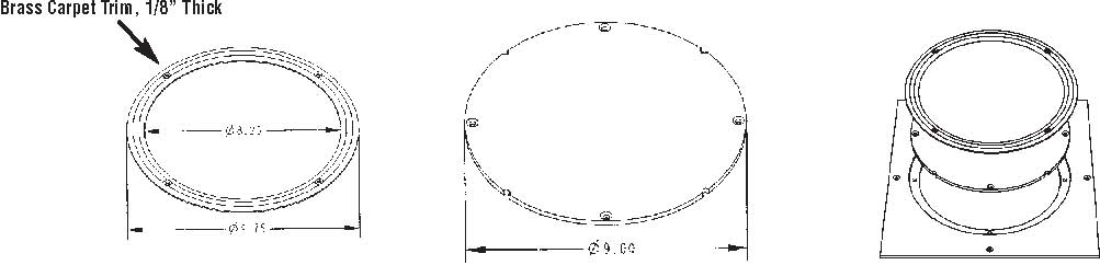
Junction Box Catalog Numbers
Carpet: 20_-JB*-RCB *=Insert Height

Raceway SolutionsTM
Conventional Underfloor Duct
Cat.No. Description
| 201-ECS | Standard Single Cell Duct |
|---|---|
| 201W-ECS | Wide Single Cell Duct |
| 202-ECS | Two Cell Duct |
| 203-ECS | Three and Four Cell Duct |
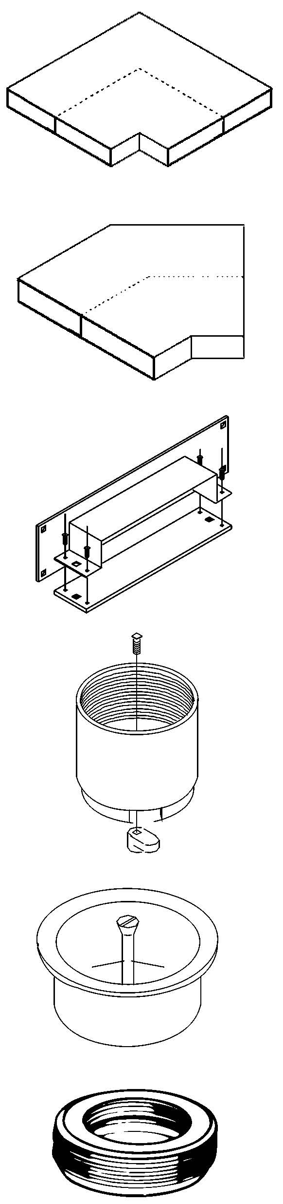
Raceway Solutions End Cap/Supports provide a means of supporting and closing unused duct ends. Material: 14 gauge pre-galvanized steel with 668 coating UL Listing No. 668
Cat.No. Description
| 201-UCA | Standard Single Cell Duct |
|---|---|
| 201W-UCA | Wide Single Cell Duct |
| 202-UCA | Two Cell Duct |
| 203-UCA | Three Cell Duct |
| 204-UCA | Four Cell Duct |
Raceway Solutions End Conduit Adapters are provided with a removable blank cover which is field punched for the required combination of conduits. Conduit adapters for multi-compartment duct are supplied with interior barriers to maintain separation between services.
Cat.No. Description
| JB-CCA-B | With Removable Blank Cover |
|---|---|
| JB-CCA-1/2 | With pre-punched ½" k.o. |
| JB-CCA-3/4 | With pre-punched ¾" k.o. |
| JB-CCA-1 | With pre-punched 1" k.o. |
| JB-CCA-1-1/2 | With pre-punched 1½" k.o. |
| JB-CCA-2 | With pre-punched 2" k.o. |
Features a 16 gauge galvanized steel removable cover that may be field punched for required conduit. Material: 14 gauge pre-galvanized steel with 668 coating UL Listing No. 668
Cat.No. Description 201-VEL Standard Single Cell Duct
| 201W-VEL | Wide Single Cell Duct |
|---|---|
| 202-VEL | Two Cell Duct |
| 203-VEL | Three Cell Duct |
| 204-VEL | Four Cell Duct |
Material: 14 gauge pre-galvanized steel with 668 coating UL Listing No. 668

Raceway SolutionsTM
Conventional Underfloor Duct
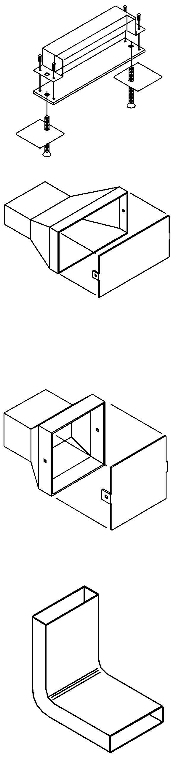
Cat.No. Description
| 201-HB90 | Standard Single Cell Duct |
|---|---|
| 201W-HB90 | Wide Single Cell Duct |
| 202-HB90 | Two Cell Duct |
| 203-HB90 | Three Cell Duct |
| 204-HB90 | Four Cell Duct |
Cat.No. Description
| 201-DCC | Standard Single Cell Duct |
|---|---|
| 201W-DCC | Wide Single Cell Duct |
| 202-DCC | Two Cell Duct |
| 203-DCC | Three and Four Cell Duct |
Material: 14 gauge pre-galvanized steel with 668 coating UL Listing No. 668
Cat.No. Height
DAI-1 1"
DAI-2 2"
DAI-3 3"
DAI-4 4"
Material: Zinc die cast
Cat.No. Description DMC-Z Insert marker cap with zinc screw
DMC-B Insert marker cap with brass screw
Material: 14 gauge pre-galvanized steel with 668 coating UL Listing No. 668
Cat.No. Description RB-162 2" to ¾"
RB-163 2" to 1"
Material: Steel, Zinc Plated UL Listing No. E-1275

Raceway SolutionsTM
Conventional Underfloor Duct
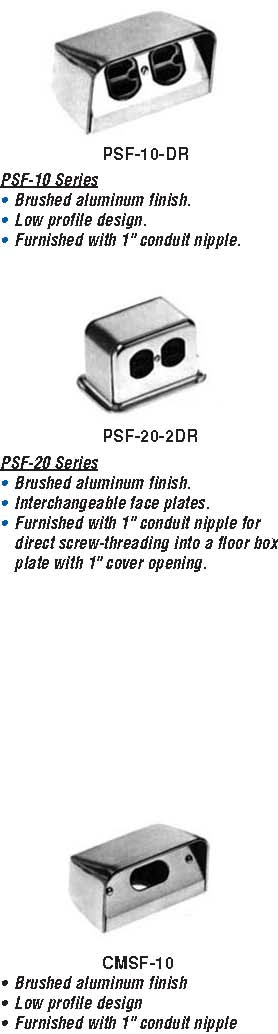
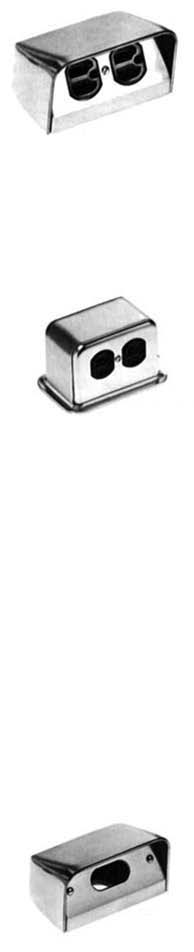
Service Head Fittings
Raceway Solutuions service fittings provide and data. A variety of service fitting above-floor service for power, communications designs are available.
| Cat. No. | Description | Finish | Dimensions Wt. W D H (lbs.) 4⅜" 3" 2⅝" 1.6 | |||||
|---|---|---|---|---|---|---|---|---|
| 4⅜" 5" | 3" 3⅜" | 2⅝" 3" | 1.5 1.38 | |||||
| 5" 5" | 3⅜" 3⅜" | 3" 3" | 1.25 1.25 | |||||
| PSF-10-DR | Furnished with one 15 am | p, | Brushed | |
|---|---|---|---|---|
| 125 volt, 3-wire NEMA | Aluminum | |||
| duplex receptacle | ||||
| PSF-10 | Same as PSF-10-DR | Brushed | ||
| above less duplex recepta | cle | Aluminum | ||
| PSF-20-2DR | Furnished with two back t | o back | Brushed | |
| 15 amp, 125 volt, 3 wire N | EMA | Aluminum | ||
| duplex receptacles | ||||
| PSF-20 | Same as PSF-20-2DR les | s | Brushed | |
| duplex receptacles | Aluminum | |||
| PSF-21 | Furnished with cover plate | to | Brushed | |
| accommodate one 30 or 50 amp, | Aluminum | |||
| 240 volt, 3 wire receptacle and | ||||
| blank cover | ||||
| PSF-20 Series Component Parts | ||||
PSF-20-BASE Standard above floor service fitting base only. PSF-20-TELEDVP Device plate for PSF-20 with 1" dia. hole. PSF-20-DUPDVP Device plate for PSF-20 for duplex. PSF-20-BLDVP Blank device plate for PSF-20. PSF-20-DVP139 Device plate for PSF-20 with 1⁄" dia. hole.
UL Listing No. 514A
Duplex Telephone Plate,
Blank Single Receptacle Single Receptacle Receptacle Plate 1" Hole Plate, 1.39" Hole Plate, 1.60" Hole Plate
PSF-20-Base PSF-20
PSF-20-BLDVP PSF-20-PSF-20-PSF-20
TELEDVP DVP139 DVP160 DUPDVP
| Cat. | Dimensions | Wt. | ||||
|---|---|---|---|---|---|---|
| No. | Description | Finish | W | D | H | (lbs.) |
| CMSF-10 | 3⁄4 "x 1⅛" bushed opening for | Brushed | 4⅜" | 3⅛" | 2⅝" | 1.5 |
| telephone or computer | Aluminum | |||||
| UL Listing No. 514A | ||||||

Raceway SolutionsTM
Conventional Underfloor Duct Specifications
Part 1 -GENERAL
1.1 SUMMARY
Work under this section includes all labor and materials which are required for the completion of infloor distribution system, as shown on drawings and as specified. The Conditions of the Contract apply to this section as fully as if repeated herein.
1.1.1 Work includes, but is not necessarily limited to the following principal items.
a.Raceway Solutions metal underfloor raceway.
b.Related accessories, to include junction boxes,supports, closures, and all other items necessary to the Raceway Solutions system.
1.2 REFERENCES: The editions of specifications and standards referenced herein, published by the following organizations, apply to the work only to the extent specified by the reference.
- a.
- Underwriters Laboratories,Inc. (UL Standard 884)
- b.
- National Electric Code (NFPA No. 70)
1.3 QUALITY ASSURANCE:
1.3.1 Standards:
.1 The material, products and equipment specified in this section establish a standard of quality of required function, dimension, appearance and quality to be met by any proposed substitution.
.2 The manufacturer and installer shall demonstrate a minimum of five years experience with this type of underfloor duct system.
1.4 SUBSTITUTIONS:
1.4.1 No substitution will be considered unless written request for approval has been submitted by the bidder and has been received by the Architect at least ten (10) days prior to the date for receipt of bids.
1.4.2 Each such request shall include the name of the materials or equipment for which it is to be substituted and a complete description of the proposed substitute including drawings, cuts, mock-ups, performance and test data, compliance with codes and approvals and any other information necessary for evaluation.
1.5 SUBMITTALS:
1.5.1 Manufacturer’s Data: Submit manufacturer’s specifications and installation instructions for each product specified. Include manufacturer’s certification as may be required to show compliance with these specifications. Indicate by transmittal form that a copy of each instruction has been distributed to the installer.
1.5.2 Shop Drawings:
.1 Submit detailed drawings showing layout of all Raceway Solutions raceways, junction boxes, and accessories as necessary for the proper installation of the infloor system.
PART 2 -PRODUCTS
2.1 RACEWAY SOLUTIONS RACEWAY
2.1.1 Typical module as shown on drawings consisting of 1, 2, 3 or 4 compartment raceways.
2.1.2 Materials: Raceway Solutions duct shall be fabricated from 14 (2mm) gauge steel.
2.1.3 Capacity: Raceway Solutions 201 Series Raceway shown have outside dimensions of 3½" x 1½". 201W Series: 5⅞" x 1½" 202 Series: 10" x 1½" 203 Series: 15" x 1½" 204 Series: 15" x 1½"
2.1.4 Raceway Solutions Fabrication:
.1 The Raceway Solutions duct units shall be manufactured in maximum lengths of 10’ (3048 mm).
.2 Protective Coating: The Raceway Solutions duct shall be coated for corrosion resistance.
2.1.5 Preset Inserts: .1 Preset inserts shall be mounted 12"
(304.8 mm) or 24" (609.6 mm) on center on the Raceway Solutions duct raceway.
.2 The preset inserts shall be made of zinc die cast, and shall be a minimum of 1" (25.4 mm) over top of the duct.
.3 The preset inserts will have an inside diameter of 2" (50.8) IPS capable of housing 2" (50.8 mm) conduit.
.4 The preset inserts shall have a beveled base which is expanded into the duct to form a continuous passageway.
.5 Each preset insert will have a removable cap that is recessed to receive concrete.
2.1.6 Junction Boxes:
.1 The junction boxes shall have openings in all 4 corners for conduit adapters.
.2 The junction box shall have pre-pour adjustment (vertical and angular) via 4 leveling legs.
.3 The junction box shall be supplied with integral aluminum tile trim.
.4 All duct and conduit connections shall be completely grounded via a grounding screw.
.5 Junction box shall contain inclusive tile trim.
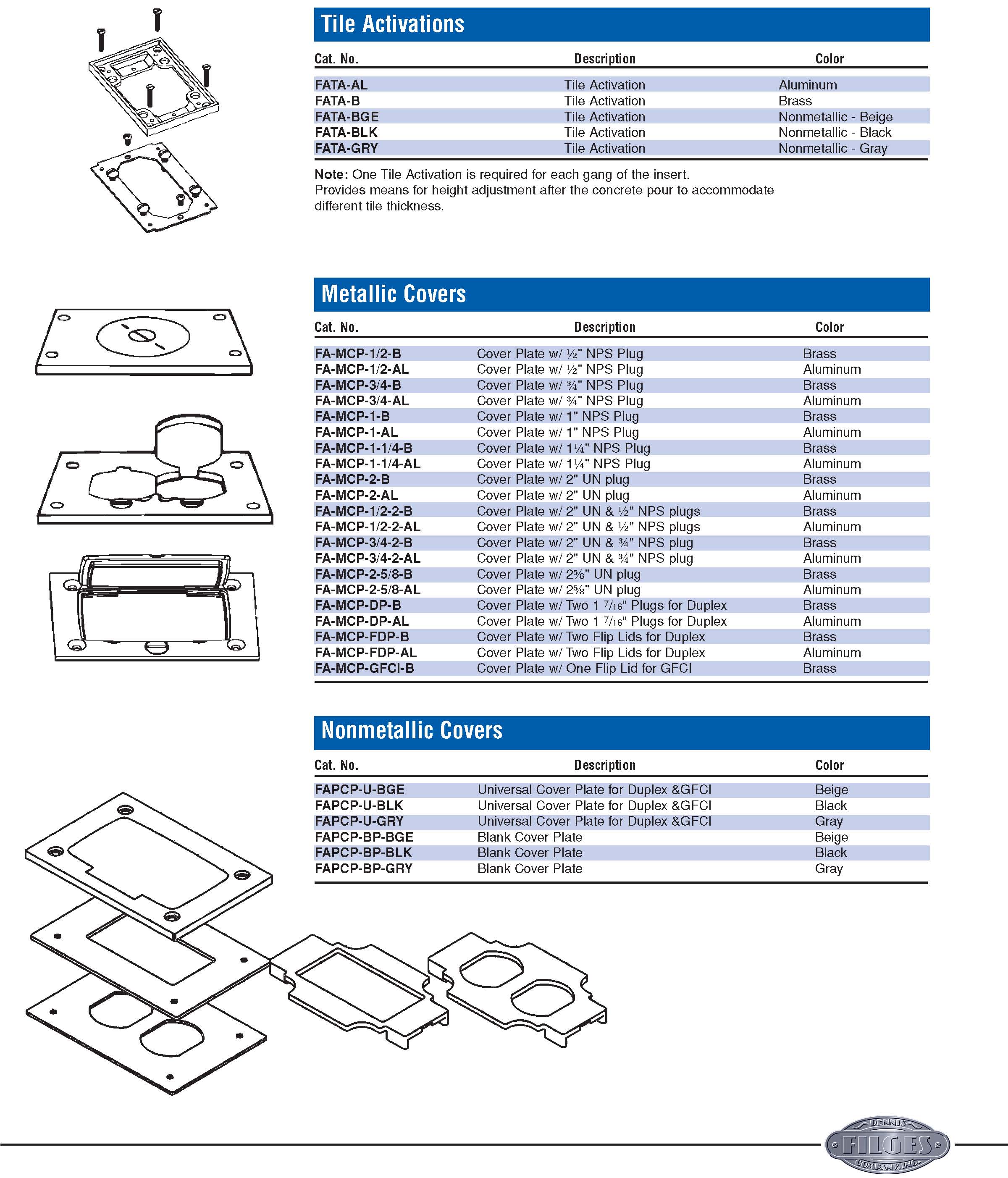
2.2 ACTIVATIONS
2.2.1 Supply activation assemblies as requested.
2.2.2 The manufacturer shall supply the necessary pieces to transition from the 2" (50.8 mm) I.P.S. preset to the service fitting upon request.
2.2.3 Activation assemblies shall be Raceway Solutions PSF-20 series, PSF-10 series, CMSF-10 series HELP
- Activation assemblies shall be pedestal style (as specified).
- RACEWAY SOLUTIONS UNDERFLOOR DUCT INSTALLATION
3.1.1 Install distribution raceway system and accessories in accordance with the manufacturer’s recommendation, installation instructions, the final installation drawings and as herein specified. Electrical module lines shall be laid out on the concrete base in each building bay and the raceway units shall be located in strict accordance with the electrical drawings in order to

Raceway SolutionsTM
Conventional Underfloor Duct Specifications
| maintain the electrical module | Article 354 of the National Electric | PART 4 -MANUFACTURER: |
| spacing. | Code. | 4.1 Acceptable Brands: |
| 3.1.2 Place raceway system on the | 3.3 CONCRETE PLACEMENT: | a. Raceway Solutions by Dennis Filges |
| supporting framework and adjust to | 3.3.1 Concrete topping shall be as | Co. Inc.. |
| final position with proper end bearing | indicated on the drawings and as | b.Other suppliers must submit 10 |
| and alignment at the butt joints before | specified under Section 03300. | days prior for approval. |
| permanent fastening. All joints shall | Concrete containing chlorides from | |
| be secured with grounding screws. | any source shall not be placed over | |
| 3.1.3 Permanently fasten the raceway | infloor units. | |
| supports to the supporting framework | 3.3.2 Before concrete placement, | |
| with screws and nails. Spacing | make a final inspection of the entire | |
| between support shall not exceed 5’ | Raceway Solutions system. Any gaps | |
| 0" (1524 mm). | in the system shall be sealed to pre | |
| 3.1.4 The raceway supports and the | vent mortar or concrete from entering. | |
| raceway distribution system shall be | 3.3.3 Reinforced concrete design | |
| adjusted so the top of the presets are | shall be in accordance with American | |
| 1/8 (3.2 mm) inch to 3/8 (9.5 mm) inch | Concrete Institute Specifications for | |
| below the screed line. | Structural Concrete for Buildings | |
| 3.1.5 Marker screw caps shall be | (ACI301-72) and ACI Building Code | |
| used in place of the standard insert | Requirements for Reinforced | |
| caps at the following locations: (a) in | Concrete (ACI1318-83). Concrete | |
| each insert adjacent to a junction box; | placement shall follow proper and | |
| (b) in inserts on each side of a | accepted industry practice and be in | |
| permanent wall, and (c) in the last | accordance with ACI Recommended | |
| insert in each run of duct. | Practice for Measuring, Mixing, | |
| 3.1.6 Do not use the installed raceway | Transporting and Placing Concrete | |
| system for working platforms or | (ACI304-73), Concrete must be | |
| walkways. | vibrated at all headers, junction | |
| 3.1.7 After placing of concrete fill and | boxes, and raceway to insure that the | |
| before wiring is installed, remove | concrete completely fills underneath | |
| debris and other foreign materials. | the Raceway Solutions system. | |
| 3.1.8 If moisture is present, remove | However, it is imperative that the con- | |
| cover plates as necessary to allow air | crete not be over vibrated. Over vibra | |
| circulation. | tion causes segregation of materials in | |
| 3.2 FIELD QUALITY CONTROL: | the concrete mix which in turn leads to | |
| 3.2.1 Field testing and inspection are | weakening of concrete strength. | |
| specified in Section 01410. | 3.3.4 Shrinkage and temperature | |
| 3.2.2 Protection: Protect installation of | reinforcement above the Raceway | |
| floor system from damage. Do not | Solutions system shall be in accor | |
| allow equipment or heavy traffic over | dance with ACI318-83. Care shall be | |
| Raceway Solutions duct during con- | taken during concrete placement and, | |
| struction period, without first installing | in particular, during concrete vibration, | |
| ramps over the duct. Ramps shall be | to prevent rising of top reinforcement | |
| designed so that imposed loads are | within the slab. | |
| not transferred to Raceway Solutions | 3.3.5 Contractors placing the | |
| duct. Replace components of the sys | concrete shall carefully hand finish a | |
| temwhich are damaged during | minimum of 24" (609.6 mm) adjacent | |
| construction, at no cost to the Owner. | to junction box access openings, so | |
| 3.2.3 The installed Raceway Solutions | that the top of finished concrete and | |
| raceway system shall be U.L. Listed | junction box access units are flush. | |
| Under Standard 884 and shall comply with |

Raceway SolutionsTM
Conventional Underfloor Duct Specifications
| 4.875 Sq.In.Compartment | |||||||
|---|---|---|---|---|---|---|---|
| Conductor | RHW/RHH | TW | THW | THWN | XHHW | ||
| 14 12 10 | 75 55 45 | 140 108 80 | 93 75 59 | 201 147 92 | 140 108 80 | ||
| 5.4375 Sq.In.Compartment | |||||||
| Conductor | RHW/RHH | TW | THW | THWN | XHHW | ||
| 14 12 10 | 84 62 50 | 156 120 90 | 104 84 65 | 224 164 103 | 156 120 99 | ||
| 6.0 Sq.In.Compartment | |||||||
| Conductor | RHW/RHH | TW | THW | THWN | XHHW | ||
| 14 12 10 | 92 68 55 | 173 133 99 | 115 92 72 | 247 180 114 | 173 133 99 | ||
| 7.5 Sq.In.Compartment | |||||||
| Conductor 14 12 10 | RHW/RHH 115 85 69 | TW 216 166 123 | THW 144 115 90 | THWN 309 226 142 | XHHW 216 166 123 | ||
| Conductor | RHW/RHH | 8.8125 Sq.In.Compartment TW THW THWN | XHHW | ||||
| 14 12 10 | 136 100 81 | 254 195 145 | 169 136 106 | 363 265 167 | 254 195 145 | ||
| 10.125 Sq.In.Compartment | |||||||
| Conductor | RHW/RHH | TW | THW | THWN | XHHW | ||
| 14 12 10 | 156 115 93 | 291 224 167 | 194 156 122 | 418 305 192 | 291 224 167 | ||
Number of allowable conductors at 40% fill.
Estimating Raceway Solutions Conventional Underfloor Duct
Step 1: Determine the total number of feet of duct you’ll need for your space.
Step 2: Calculate the number of pieces of duct necessary by dividing the total number of feet by 10. Always round up to the next whole number.
Example: Total length of duct = 226 feet 226'/10' = 22.6 pcs.Total number of pieces required for the job is 23.
Step 3: Determine number of junction boxes and accessories necessary for the system.
- Duct Couplers/Supports – one for every 5’ of duct.
- Duct End Cap/Supports – close off unused duct ends.
- Conduit Adapters – enters either the junction box or duct end.
- Afterset inserts – used primarily with blank duct.
- Service heads – PSF - series, CMSF-series or none.

Raceway SolutionsTM
Flush Activation Underfloor Duct
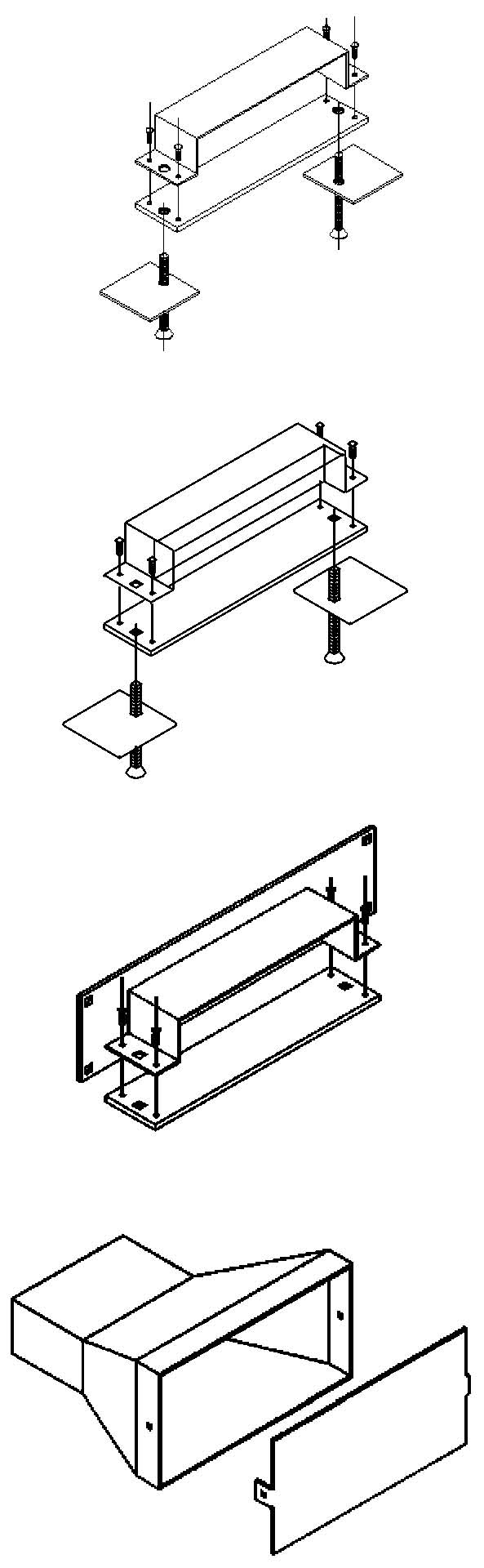
Raceway Solutions Flush Activation Underfloor Duct provides an aesthetic wire management solution for delivering power and communications services. The new flush-style inserts, which use standard floor box covers for power and data outlets, make it the ideal underfloor duct solution for office environments, retail locations, casinos, and medical facilities. Raceway Solutions Flush Activation Underfloor Duct sets the standard for fast, easy installation by incorporating a unique one-piece duct design along with integral coupler/supports.
Raceway Solutions Flush Activation Underfloor Duct also sets the standard for application flexibility. The duct comes with activation inserts pre-assembled to the duct, or the inserts can be purchased separately for field installation only where you need them. Unique multi-gang inserts with removable voltage dividers provide the flexibility of installing multiple gangs of the same service at each insert location. In addition, the use of standard floor box covers enables a wide variety of power and data outlets.
Features & Benefits:
• Available in 1-, 2-, and 3- compartment duct configurations
Unique one-piece duct reduces installation labor.
Welded-in dividers create separate channels for power & communications services.
• Unique multi-gang inserts offer application flexibility
Removable voltage dividers allow multiple gangs of the same service at each insert
location.
Individual gangs can be activated as needed – keeps costs down.
Afterset inserts are available for field installation – inserts only where you need them
to minimize system cost.
• Aesthetic, flush-mounted activation trims are available for both carpet and tile applications
Brass, aluminum and nonmetallic trims are available.
Tile trims have after-pour adjustability to accommodate variations in tile thickness.
• Activation trims accept standard Raceway Solutions Floor Box Covers
Brass, aluminum and nonmetallic covers are available.
Complete cover offering accommodates a wide range of applications.
• Combination coupler/supports simplify installation
Same part is used to join raceway sections together and to support/level the duct –
reduces labor & material.

Raceway SolutionsTM
Flush Activation Underfloor Duct
20_F -3-12
# of Cells Insert Height Insert Spacing
1 = Single Cell B = Blank 1W = Single Cell Wide 15 = 1½” Height 12 & 24 Standard 2 = Two Cell 2 = 2” Height 6, 18, & 36 (optional) 3 = Three Cell 3 = 3” Height
Cat.No. Duct Depth Duct Width Compartment Width Insert Height Insert Spacing
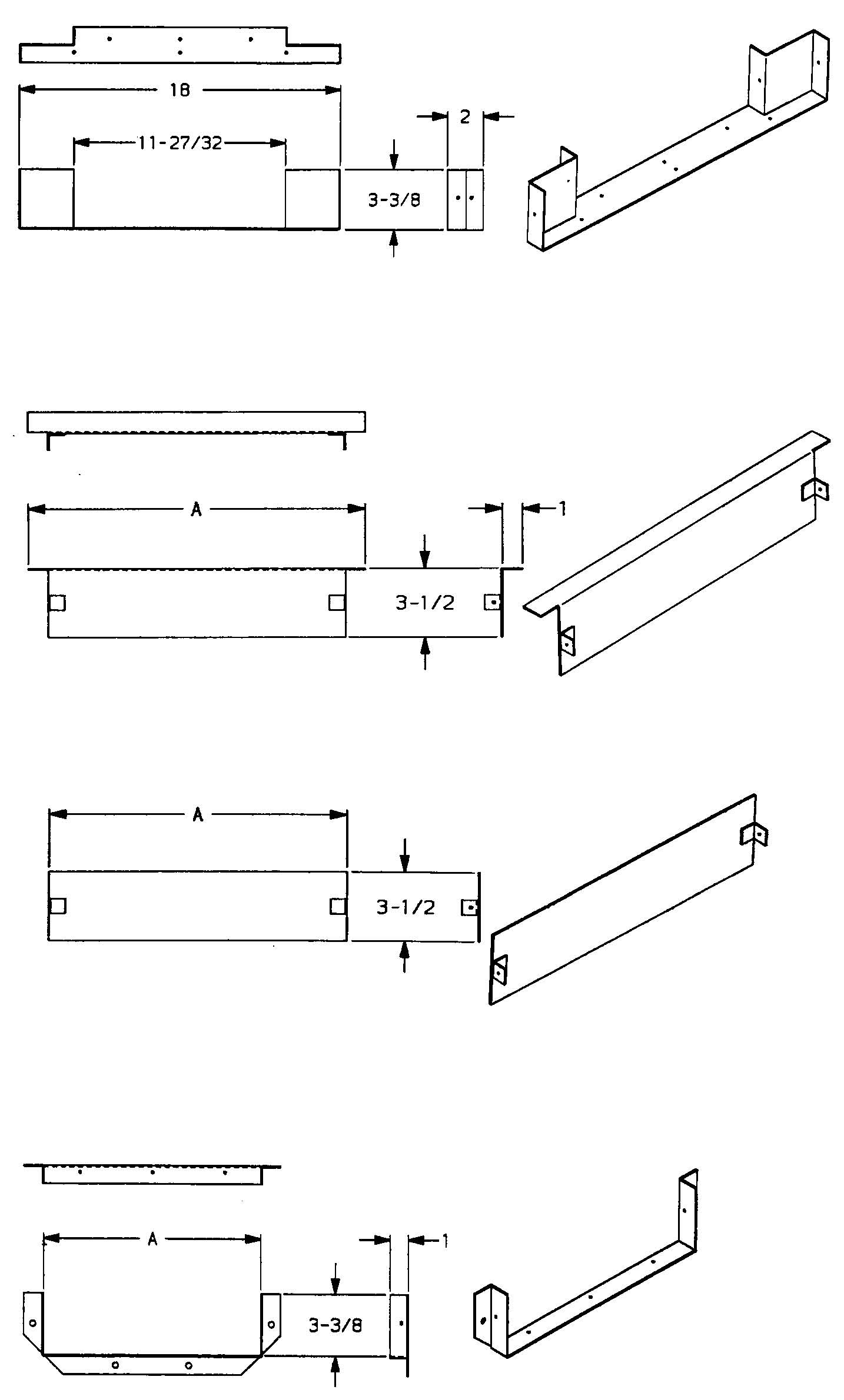
201-B 1½"3¼" A =3¼" (no inserts) (no inserts) 201F-3-24 1½"3¼" A =3¼" 3" 24" 201F-2-24 1½"3¼" A =3¼" 2" 24" 201F-15-24 1½"3¼" A =3¼"1½" 24" 201F-3-12 1½"3¼" A =3¼" 3" 12" 201F-2-12 1½"3¼" A =3¼" 2" 12" 201F-15-12 1½"3¼" A =3¼"1½" 12" 201W-B 1½"5⅞" A =5⅞" (no inserts) (no inserts) 201WF-3-24 1½"5⅞" A =5⅞" 3" 24" 201WF-2-24 1½"5⅞" A =5⅞" 2" 24" 201WF-15-24 1½"5⅞" A =5⅞"1½" 24" 201WF-3-12 1½"5⅞" A =5⅞" 3" 12" 201WF-2-12 1½"5⅞" A =5⅞" 2" 12" 201WF-15-12 1½"5⅞" A =5⅞"1½" 12" 202-B 1½" 10" A & B = 5" (no inserts) (no inserts) 202F-3-24 1½" 10" A & B = 5" 3" 24" 202F-2-24 1½" 10" A & B = 5" 2" 24" 202F-15-24 1½" 10" A & B = 5" 1½" 24" 202F-3-12 1½" 10" A & B = 5" 3" 12" 202F-2-12 1½" 10" A & B = 5" 2" 12" 202F-15-12 1½" 10" A & B = 5" 1½" 12" 203F-B 1½" 15" A & C = 6"- B =3" (no inserts) (no inserts) 203F-3-24 1½" 15" A & C = 6"- B =3" 3" 24" 203F-2-24 1½" 15" A & C = 6"- B =3" 2" 24" 203F-15-24 1½" 15" A & C = 6"- B =3" 1½" 24" 203F-3-12 1½" 15" A & C = 6"- B =3" 3" 12" 203F-2-12 1½" 15" A & C = 6"- B =3" 2" 12" 203F-15-12 1½" 15" A & C = 6"- B =3" 1½" 12"
All duct sections 10’ long, 14 gauge pre-galvanized steel.
Cat. No. Description
201-JB-3 Junction box for 201 Series Duct with 3" high inserts 201-JB-2 Junction box for 201 Series Duct with 2" high inserts 201-JB-15 Junction box for 201 Series Duct with 1½" high inserts 201W-JB-3 Junction box for 201W Series Duct with 3" high inserts 201W-JB-2 Junction box for 201W Series Duct with 2" high inserts 201W-JB-15 Junction box for 201W Series Duct with 1½" high inserts 202-JB-3 Junction box for 202 Series Duct with 3" high inserts 202-JB-2 Junction box for 202 Series Duct with 2" high inserts 202-JB-15 Junction box for 202 Series Duct with 1½" high inserts 203F-JB-3 Junction box for 203F Series Duct with 3" high inserts 203F-JB-2 Junction box for 203F Series Duct with 2" high inserts 203F-JB-15 Junction box for 203F Series Duct with 1½" high inserts

Raceway SolutionsTM
Flush Activation Underfloor Duct
Cat. No. Description
201-DCS Duct Coupler/Support for 201 Series Duct 201W-DCS Duct Coupler/Support for 201W Series Duct 202-DCS Duct Coupler/Support for 202 Series Duct 203-DCS Duct Coupler/Support for 203F Series Duct
Provides means for coupling duct sections together and for supporting the duct system. It is recommended that a support/coupler be used every 5' of duct run. Material: 14 gauge pre-galvanized steel
Cat. No. Description
201-ECS Duct End Cap/Support for 201 Series Duct 201W-ECS Duct End Cap/Support for 201W Series Duct 202-ECS Duct End Cap/Support for 202 Series Duct 203-ECS Duct End Cap/Support for 203F Series Duct
Provides means for supporting and closing off unused duct ends. Material: 14 gauge pre-galvanized steel
Cat. No. Description
| 201-DCC | Duct Cabinet Connector for 201 Series Duct |
|---|---|
| 201W-DCC | Duct Cabinet Connector for 201W Series Duct |
| 202-DCC | Duct Cabinet Connector for 202 Series Duct |
| 203-DCC | Duct Cabinet Connector for 203F Series Duct |
Provides means for connecting duct to an electrical cabinet. Material: 14 gauge pre-galvanized steel
Cat. No. Description
201-UCA Universal Conduit Adapter for 201 Series Duct 201W-UCA Universal Conduit Adapter for 201W Series Duct 202-UCA Universal Conduit Adapter for 202 Series Duct 203F-UCA Universal Conduit Adapter for 203F Series Duct
Provides means for attaching conduit to the underfloor duct system at the junction box. The conduit adapter is inserted into a main duct entrance. The blank cover can be field-punched for the required combination of conduits. Material: 14 gauge pre-galvanized steel

Raceway SolutionsTM
Flush Activation Underfloor Duct
Cat. No. Description
JB-CCA-B Corner Conduit Adapter with blank cover JB-CCA-1/2 Corner Conduit Adapter with ½" KO JB-CCA-3/4 Corner Conduit Adapter with ¾" KO JB-CCA-1 Corner Conduit Adapter with 1" KO JB-CCA-1-1/2 Corner Conduit Adapter with 1½" KO JB-CCA-2 Corner Conduit Adapter with 2" KO
Provides means for attaching conduit to the underfloor duct system at the junction box. The corner conduit adapter is inserted into the corner conduit entrance of any size junction box. Material: 14 gauge pre-galvanized steel
Cat. No. Description
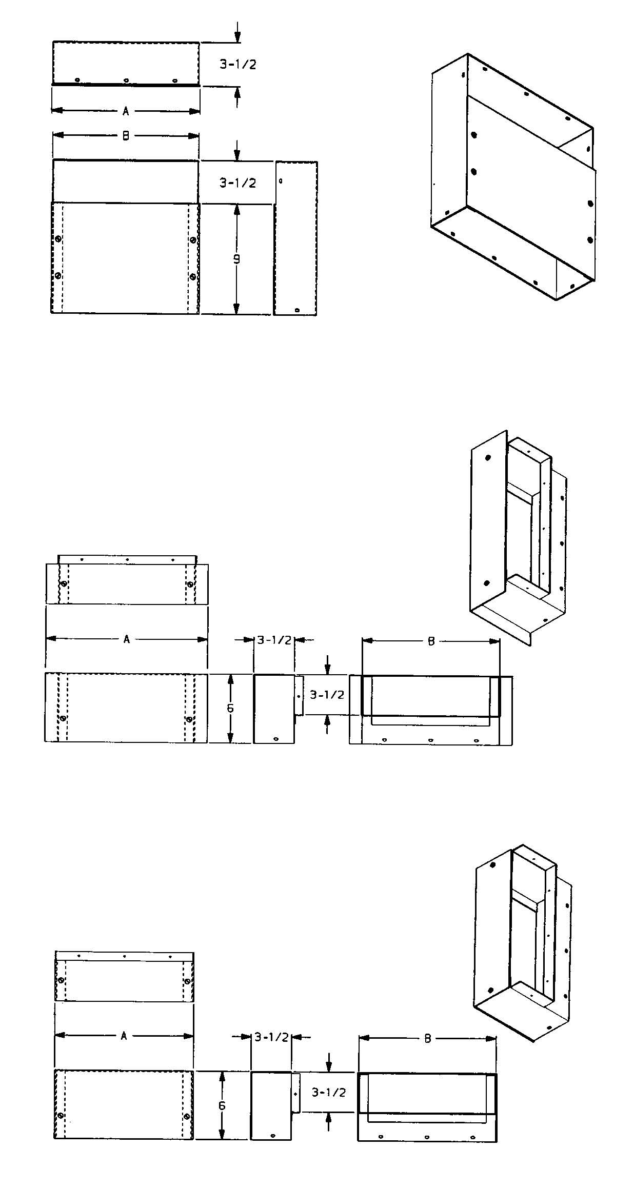
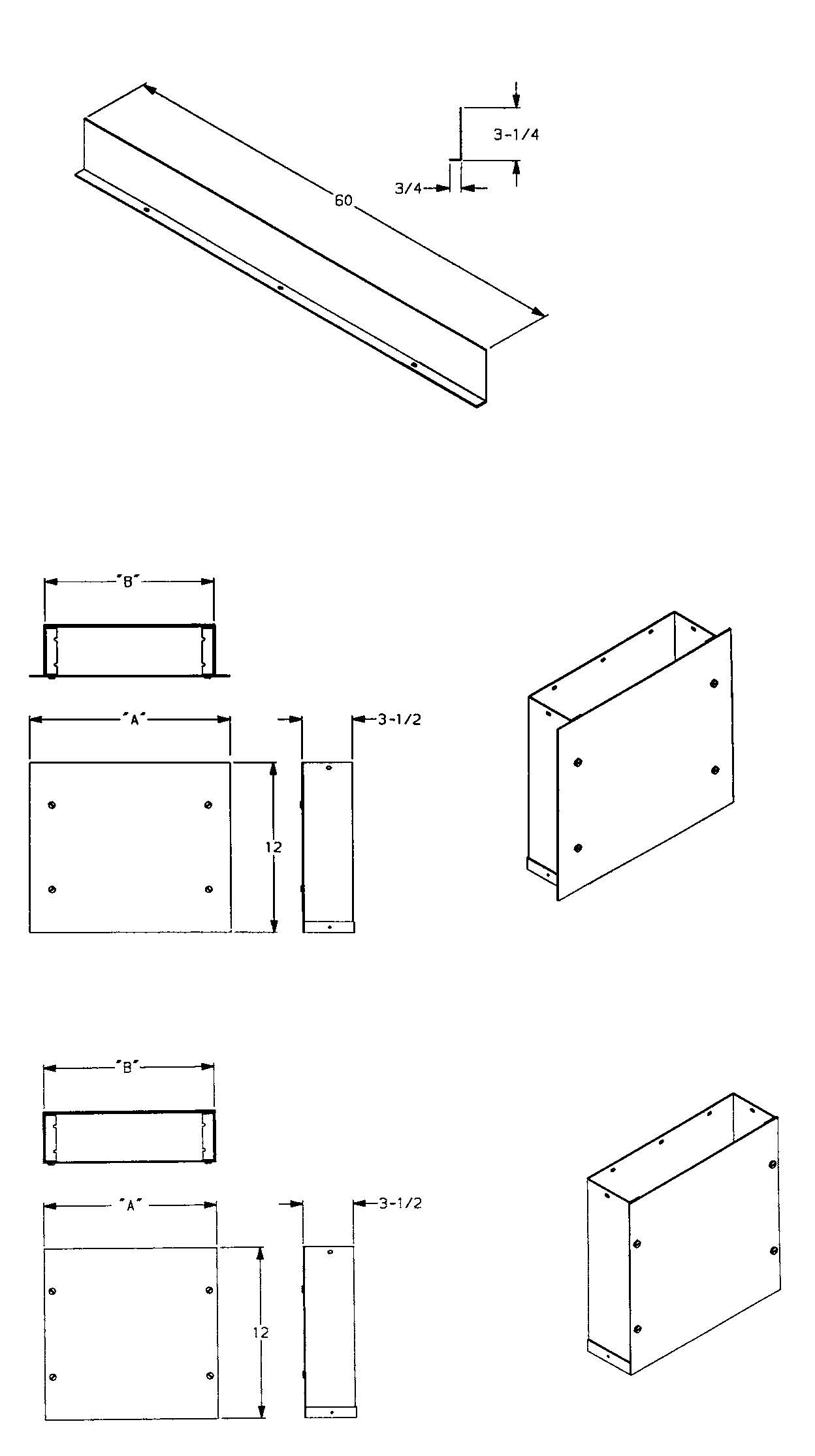
| 201-VEL | Vertical Elbow for 201 Series Duct |
|---|---|
| 201W-VEL | Vertical Elbow for 201W Series Duct |
| 202-VEL | Vertical Elbow for 202 Series Duct |
| 203F-VEL | Vertical Elbow for 203F Series Duct |
Material: 14 gauge pre-galvanized steel
Cat. No. Description
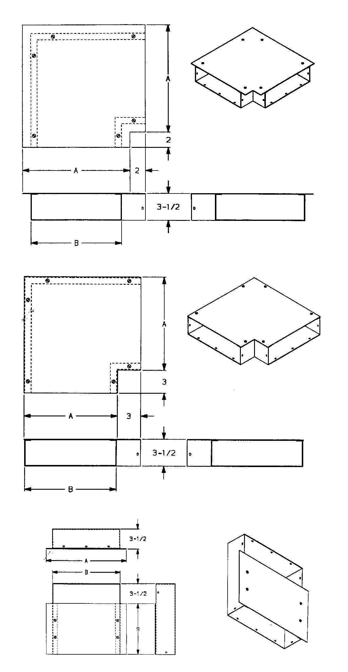
| 201-HB90 | Horizontal 90° Elbow for 201 Series Duct |
|---|---|
| 201W-HB90 | Horizontal 90° Elbow for 201W Series Duct |
| 202-HB90 | Horizontal 90° Elbow for 202 Series Duct |
| 203F-HB90 | Horizontal 90° Elbow for 203F Series Duct |
Material: 14 gauge pre-galvanized steel
| Cat. No. | Description | Color |
|---|---|---|
| FACA-1G-AL FACA-1G-B FACA-1G-BGE FACA-1G-BLK FACA-1G-GRY FACA-2G-AL FACA-2G-B FACA-2G-BGE FACA-2G-BLK FACA-2G-GRY FACA-3G-AL FACA-3G-B FACA-3G-BGE FACA-3G-BLK FACA-3G-GRY | 1-Gang Carpet Activation 1-Gang Carpet Activation 1-Gang Carpet Activation 1-Gang Carpet Activation 1-Gang Carpet Activation 2-Gang Carpet Activation 2-Gang Carpet Activation 2-Gang Carpet Activation 2-Gang Carpet Activation 2-Gang Carpet Activation 3-Gang Carpet Activation 3-Gang Carpet Activation 3-Gang Carpet Activation 3-Gang Carpet Activation 3-Gang Carpet Activation | Aluminum Brass Nonmetallic - Beige Nonmetallic - Black Nonmetallic - Gray Aluminum Brass Nonmetallic - Beige Nonmetallic - Black Nonmetallic - Gray Aluminum Brass Nonmetallic - Beige Nonmetallic - Black Nonmetallic - Gray |

Raceway SolutionsTM
Flush Activation Underfloor Duct
Raceway SolutionsTM
Flush Activation Underfloor Duct
| Cat. No. | Description | Insert Height |
|---|---|---|
| DAIFA-1G-3 | 1-Gang Afterset Insert | 3" |
| DAIFA-1G-2 DAIFA-1G-15 | 1-Gang Afterset Insert 1-Gang Afterset Insert | 2" 1½" |
| DAIFA-2G-3 DAIFA-2G-2 | 2-Gang Afterset Insert 2-Gang Afterset Insert | 3" 2" |
| DAIFA-2G-15 DAIFA-3G-3 | 2-Gang Afterset Insert 3-Gang Afterset Insert | 1½" 3" |
| DAIFA-3G-2 DAIFA-3G-15 | 3-Gang Afterset Insert 3-Gang Afterset Insert | 2" 1½" |
Provides means to add activation inserts in the field after installation of the duct. Material: 14 gauge pre-galvanized steel
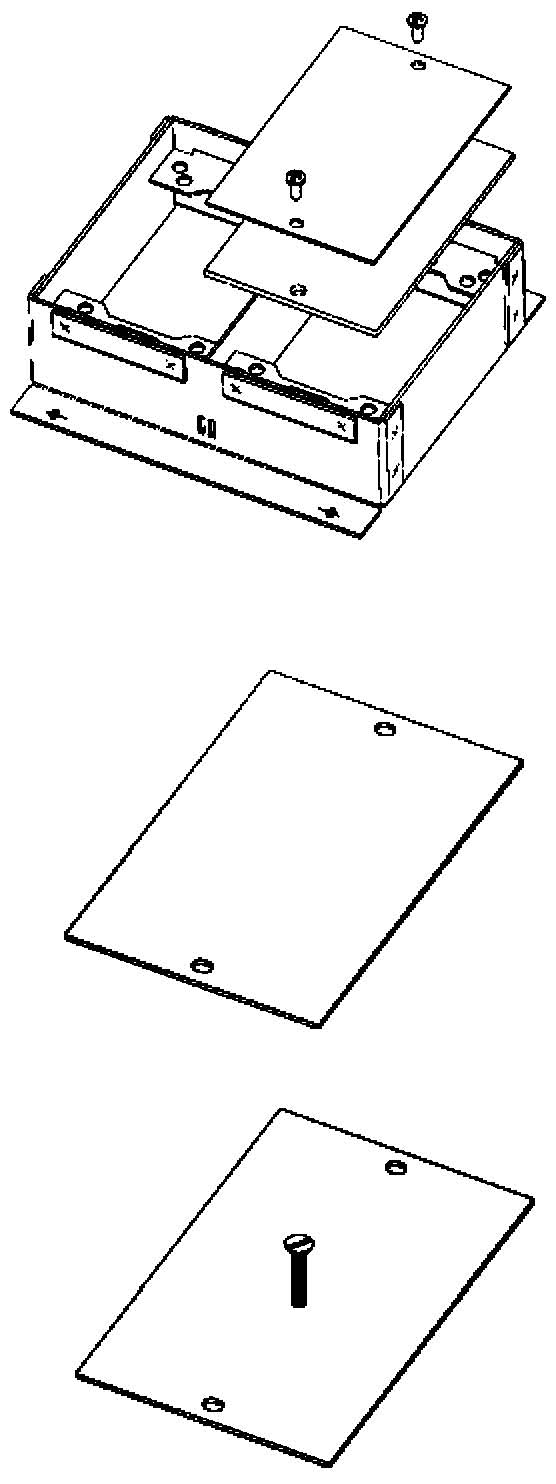
Cat. No. Description
FAD-CC Compartment Cover
Provides means to cover the opening in the duct which provides access compartment wiring. Wiring from a different compartment can then be routed into the gang and activated (used when multiple outlets of the same service are required at the same insert location). Material: 18 gauge pre-galvanized steel
Cat. No. Description
FAD-MC-Z Insert Marker Cap with Zinc Screw
FAD-MC-B Insert Marker Cap with Brass Screw

Raceway SolutionsTM
Flush Activation Underfloor Duct
| Wirefill Chart | ||||||||||
|---|---|---|---|---|---|---|---|---|---|---|
| 201 | 201W | 202 | 203F | |||||||
| CHANNEL A | CHANNEL A | CHANNEL A | CHANNEL B | CHANNEL A | CHANNEL B | CHANNEL C | ||||
| CHANNEL CROSS SECTIONAL AREA (SQUARE INCHES): | 4.38 | 7.78 | 6.60 | 6.60 | 5.90 | 4.07 | 5.90 | |||
| COAX CABLES | RG6 /u | DIA. = 0.270" | 40% FILL | 30 | 54 | 46 | 46 | 41 | 28 | 41 |
| RG11 /u | DIA. = 0.405" | 40% FILL | 13 | 24 | 20 | 20 | 18 | 12 | 18 | |
| RG58 /u | DIA. = 0.193" | 40% FILL | 60 | 106 | 90 | 90 | 80 | 55 | 80 | |
| RG59 /u | DIA. = 0.242" | 40% FILL | 38 | 67 | 57 | 57 | 51 | 35 | 51 | |
| RG62A /u | DIA. = 0.242" | 40% FILL | 38 | 67 | 57 | 57 | 51 | 35 | 51 | |
| LAN CABLES | CAT5,4 pr. UNSHIELDED | DIA. = 0.250" | 40% FILL | 35 | 63 | 53 | 53 | 48 | 33 | 48 |
| FIBER OPTIC CABLES 62.5 /125 um | 2 STRAND | DIA. = 0.175" | 40% FILL | 73 | 129 | 110 | 110 | 98 | 67 | 98 |
| 4 STRAND | DIA. = 0.175" | 40% FILL | 73 | 129 | 110 | 110 | 98 | 67 | 98 | |
| 6 STRAND | DIA. = 0.210" | 40% FILL | 50 | 89 | 76 | 76 | 68 | 47 | 68 | |
| SIGNAL CABLES | 18 AWG | DIA. = 0.066" | 40% FILL | 515 | 915 | 776 | 776 | 694 | 478 | 694 |
| 20 AWG | DIA. = 0.057" | 40% FILL | 700 | 1240 | 1050 | 1050 | 944 | 650 | 944 | |
| 22 AWG | DIA. = 0.050" | 40% FILL | 922 | 1630 | 1380 | 1380 | 1240 | 856 | 1240 | |
| 24 AWG | DIA. = 0.044" | 40% FILL | 1160 | 2070 | 1760 | 1760 | 1570 | 1080 | 1570 | |
| POWER (THHN) | 10 AWG | DIA. = 0.164" | 40% FILL | 83 | 147 | 125 | 125 | 111 | 77 | 111 |
| 12 AWG | DIA. = 0.130" | 40% FILL | 132 | 235 | 200 | 200 | 178 | 123 | 178 | |
| 14 AWG | DIA. = 0.111" | 40% FILL | 182 | 324 | 275 | 275 | 245 | 169 | 245 | |
201 Series 201W Series 202 Series 203F Series
Single Compartment Wide Single Compartment Two Compartment Three Compartment

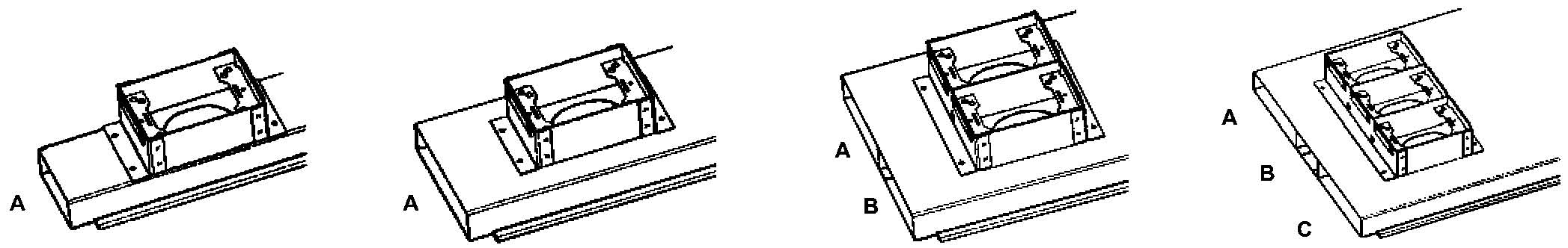
Raceway SolutionsTM
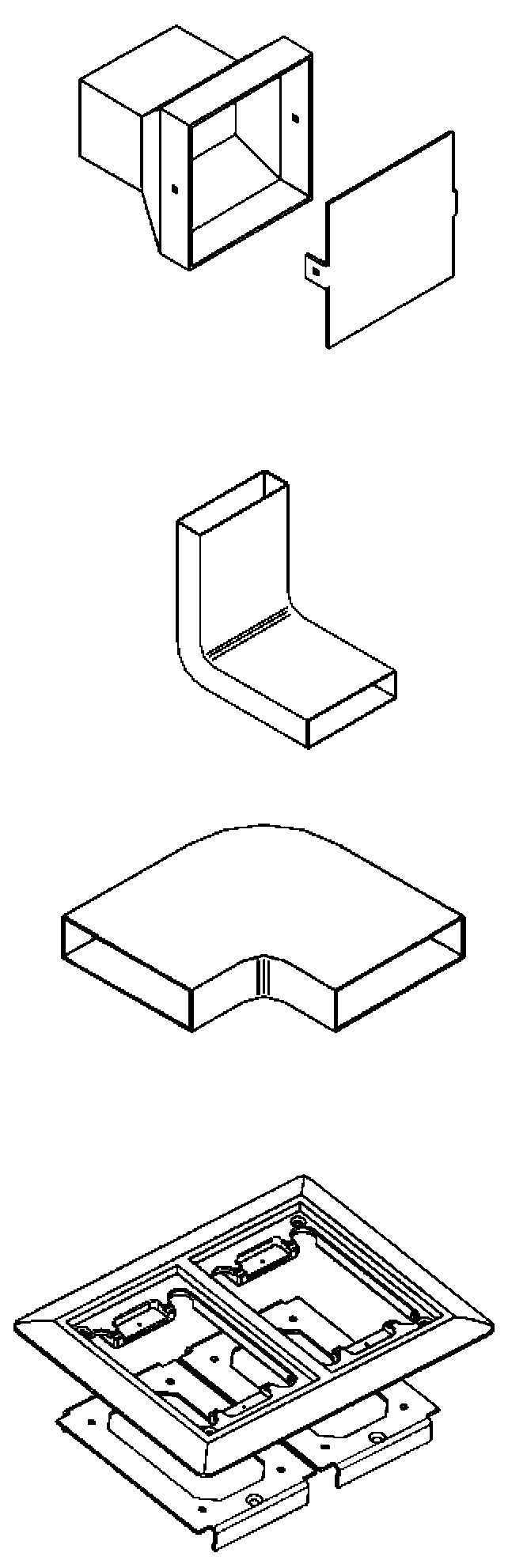
Casino Underfloor Duct
Features & Benefits
- Heavy Duty cast aluminum junction box meets the high load requirements of a casino environment (50,000 pound uniform load rating).
- Two-compartment duct provides separation of power and voice/data.
- Junction box provides individual covers for access to power and voice/data compartments.
- Attractive brass carpet trims are available for the junction box covers.
- One-piece duct configuration simplifies assembly and leveling for reduced installation costs.
- System includes a complete line of accessories and fittings for design flexibility.
- System meets the requirements of UL 884.
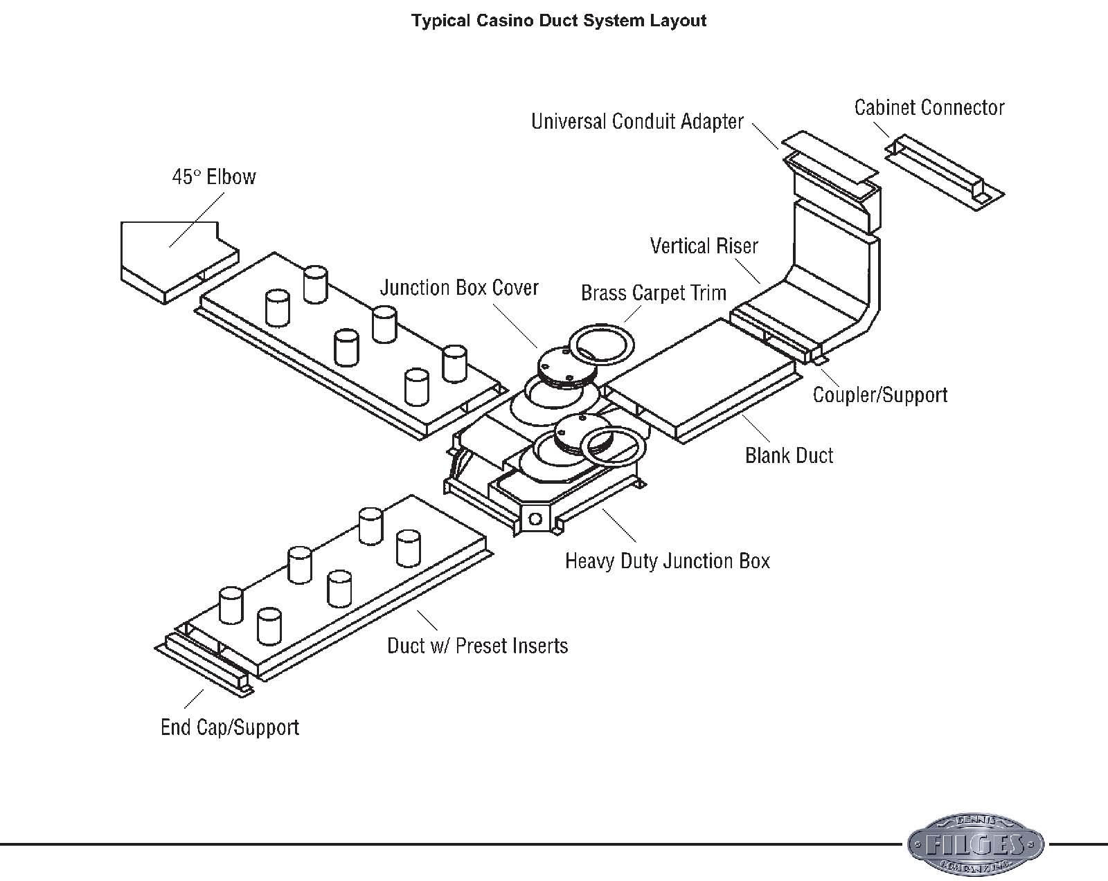
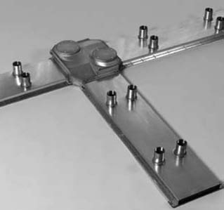
Raceway SolutionsTM
Casino Underfloor Duct
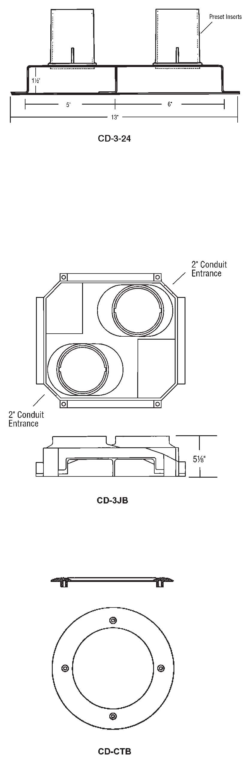
Cat. No. Description
CD-B Blank duct 10' section
CD-3-12 Duct w/ 3” presets 12” on center
CD-3-24 Duct w/ 3” presets 24” on center
NOTE: Consult factory for Casino Duct with Flush Activations.
Cat. No. Description
CD-3JB Heavy-duty cast aluminum junction box, 2 compartment.
NOTE: Consult factory for other junction box options.
Cat. No. Description
CD-CTB Brass trim ring for junction box lids.

Raceway SolutionsTM
Casino Underfloor Duct
Cat. No. Description
CD-CS For Casino Duct
Material: 14 gauge pre-galvanized steel with 668 coating UL Listing No. 668
Raceway Solutions duct coupler/supports provide a means of not only coupling duct sections together but also supporting the duct sections. It is recommended that a support/coupler be used every 5'of duct run.
Cat. No. Description
CD-ES For Casino Duct
Raceway Solutions End Cap/Supports provide a means of supporting and closing unused duct ends. Material: 14 gauge pre-galvanized steel with 668 coating UL Listing No. 668
Cat. No. Description
CD-UCA For Casino Duct
Raceway Solutions End Conduit Adapters are provided with a removable blank cover which is field punched for the required combination of conduits. Conduit adapters for multi-compartment duct are supplied with interior barriers to maintain separation between services. Material: 14 gauge pre-galvanized steel with 668 coating UL Listing No. 668
Cat. No. Description
CD-VEL For Casino Duct
Material: 14 gauge pre-galvanized steel with 668 coating UL Listing No. 668

Raceway SolutionsTM
Casino Underfloor Duct
Cat. No. Description
CD-HB90 For Casino Duct
Material: 14 gauge pre-galvanized steel with 668 coating UL Listing No. 668
Cat. No. Description
CD-HB45L 45° Elbow Left
CD-HB45R 45° Elbow Right
Material: 14 gauge pre-galvanized steel with 668 coating UL Listing No. 668
Cat. No. Description
CD-CC For Casino Duct
Material: 14 gauge pre-galvanized steel with 668 coating UL Listing No. 668
Cat. No. Description
DAI-3 3"
Cat. No. Description
DMC-Z Insert marker cap with zinc screw
DMC-B Insert marker cap with brass screw
Material: 14 gauge pre-galvanized steel with 668 coating UL Listing No. 668
Cat. No. Description
RB-162 2" to ¾"
RB-163 2" to 1"
Material: Steel, Zinc Plated UL Listing No. E-1275

Raceway SolutionsTM
Casino Underfloor Duct
Service Head Fittings
Raceway Solutions service fittings provide and data. A variety of service fitting above-floor service for power, communications designs are available.
| Cat. Dimensions Wt. No. Description Finish W D H (lbs.) PSF-10-DR Furnished with one 15 amp, Brushed 4⅜" 3" 2⅝" 1.6 125 volt, 3-wire NEMA Aluminum duplex receptacle PSF-10 Same as PSF-10-DR Brushed 4⅜" 3" 2⅝" 1.5 above less duplex receptacle Aluminum PSF-20-2DR Furnished with two back to back Brushed 5" 3⅜" 3" 1.38 15 amp,125 volt, 3 wire NEMA Aluminum duplex receptacles PSF-20 Same as PSF-20-2DR less Brushed 5" 3⅜" 3" 1.25 duplex receptacles Aluminum PSF-21 Furnished with cover plate to Brushed 5" 3⅜" 3" 1.25 accommodate one 30 or 50 amp, Aluminum 240 volt, 3 wire receptacle and blank cover SFH-20 Series Component Parts PSF-20-BASE Standard above floor service fitting base only. PSF-20-TELEDVP Device plate for PSF-20 with 1" dia. hole. PSF-20-DUPDVP Device plate for PSF-20 for duplex. PSF-20-BLDVP Blank device plate for PSF-20. PSF-20-DVP139 Device plate for PSF-20 with 1⁄" dia. hole. |
|---|
UL Listing No.514A
PSF-20-Base
Blank Plate PSF-20-BLDVP
Telephone Plate, 1" Hole PSF-20TELEDVP
Single Receptacle Plate, 1.39" Hole PSF-20DVP139
Single Receptacle Plate, 1.60" Hole PSF-20DVP160
Duplex Receptacle Plate PSF-20DUPDVP
| Cat. | Dimensions | Wt. | ||||
|---|---|---|---|---|---|---|
| No. | Description | Finish | W | D | H | (lbs.) |
| CMSF-10 | ¾"x 1⅛" bushed opening for | Brushed | 4⅜" | 3⅛" | 2⅝" | 1.5 |
| telephone or computer | Aluminum | |||||
• Low profile design.
UL Listing No.514A
• Furnished with 1" conduit nipple.

Raceway SolutionsTM
Trench Duct
Features
- High Capacity Duct
- 14 gauge galvanized steel
- Aluminum trim frame
- Total Adjustability
- Standard 3/16" steel cover plate
- Threaded groove track
- Feeds Wall Duct systems
- UL Listed No. 884
Applications
- Commercial Buildings
- Retail Outlets
- Office Buildings
- Schools, Universities
- Shopping Centers
A High-Capacity Trench System for In-Floor Wire Management
The Raceway Solutions Trench System is an in-floor wire management system that meets today’s high-capacity wiring needs that require multiple circuit separation. This system provides the raceways for which power, telecommunication and electronic circuitry can be supplied to multiple point-of-sale checkout counters, particularly those where a scanner is used or may be proposed.
Because of its ability to protect dedicated power circuits to computers as well as distribute general power in the same system, it is ideal for use in all data processing centers. Ample additional capacity for electronic, telecommunications and local area network circuitry is available.
Multiple CompartmentsProvide More Capacity ThanConventional Ducts
The Raceway Solutions trench system provides more capacity than conventional conduits and ducts. It features a single, high-capacity duct with four compartments for easy placement of additional wiring.
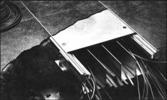
Its open-top design allows wiring to be laid in the duct instead of being pulled, eliminating the need for junction boxes. Wiring can be run directly from the top of the duct to the outlet stations, eliminating service fittings that protrude above the floor.
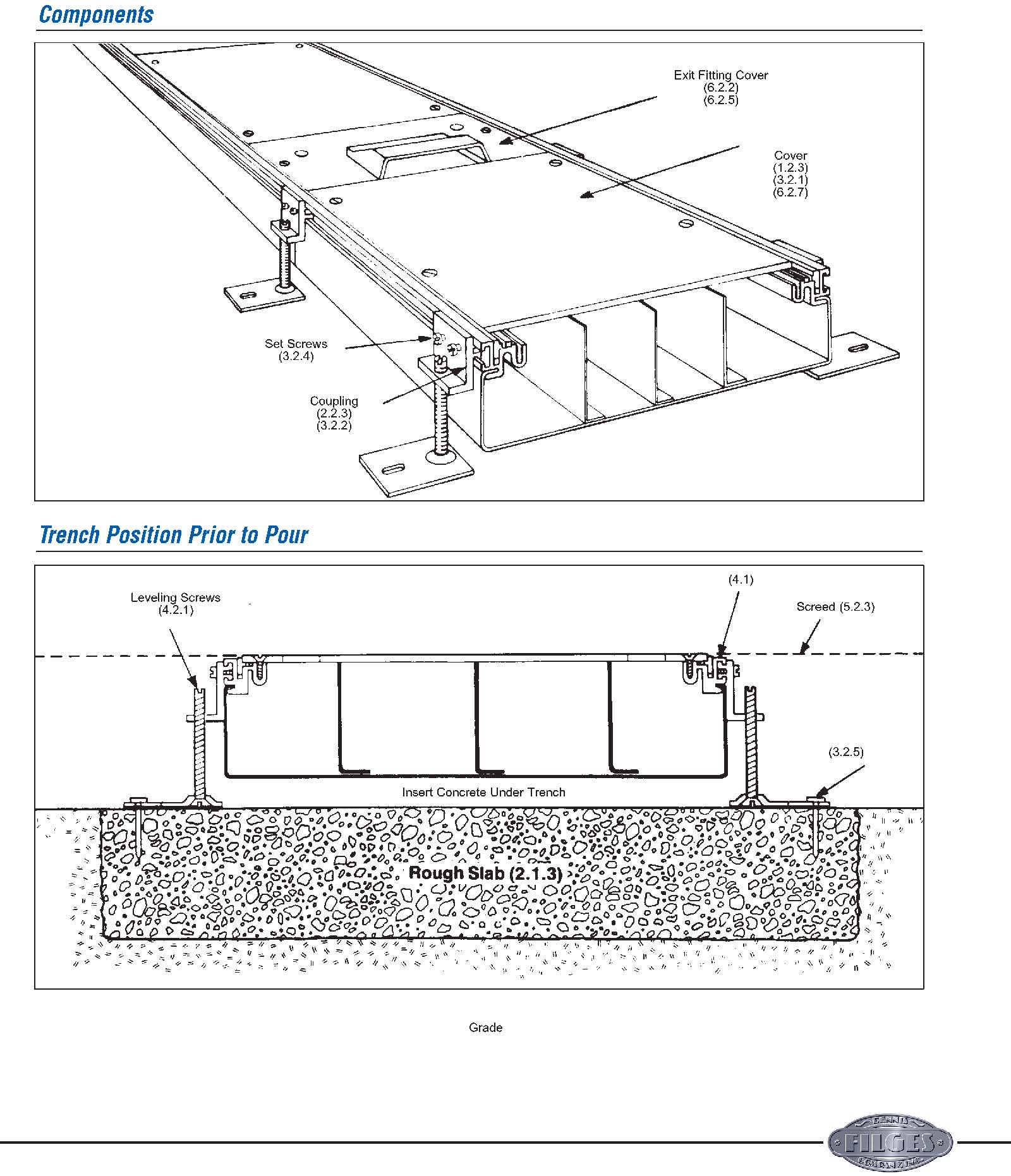
Removable covers are 3/16" thick and lock into the track of the trench preventing deflection under heavy loads.
Removable covers allow free access to wiring and can be placed anywhere along the duct for easy wire exit relocation.

Raceway SolutionsTM
Trench Duct
Duct Frame
Duct frame includes fixed metal partitions that create multiple compartments in the duct. This feature permits a single duct to distribute power, electronics and communications. Duct with fewer partitions is available to meet your specifications and can be located in strategic places to meet special distribution requirements.
The duct frame is available in a variety of sizes. The frame is of 14 gauge galvanized steel and is supplied in standard 6' lengths. It can be cut to length which increases field flexibility and eliminates the need for ordering specialty fabricated material.
Partition
Track
The track of the structural assembly integrates the base aluminum profile with the tile trim, extruded rubber strip, and the duct support assembly. The track also provides the screed line for the concrete.
• The aluminum profile accepts and holds the duct frame, rubber cushion, and cover plate screws in addition to supporting the cover plate; it also acts as a runner for the leveling screw clips.
Tile Trim
![]() Threaded Groove
Threaded Groove
- The aluminum tile trim provides a finished edge for the tile, assists in cutting, and can be reversed when the trim is not required; can be reversed when carpet is used
- The extruded rubber gasket acts as a cushion, sound dampener and moisture barrier between the cover plate and the duct; meets U.L. moptight requirements
Duct Support Assembly
The unique duct support assembly provides one time leveling capability and acts as a splice for duct sections. The assembly consists of the leveling screw clip, mounting plate, and leveling screws, and is independent of the final support of the duct.
![]() Leveling Screw Clip
Leveling Screw Clip
Leveling Screw
![]() Mounting Plate
Mounting Plate
Leveling screw allows for 1" adjustment.
- The leveling screw clip integrates with the track and provides full adjustment along the length of the duct; it also acts as the splice for duct sections
- The heavy gauge mounting plate fastens duct to metal deck,rough slab,or wood/metal forms prior to pouring concrete; it adjusts to meet most floor and installation requirements.
• The leveling screws provide vertical adjustment of the duct prior to concrete pour; this allows the duct to be leveled to the screed line so only one pour is required
Carpet
 Trim
Trim
Aluminum Profile Rubber Strip
Cover
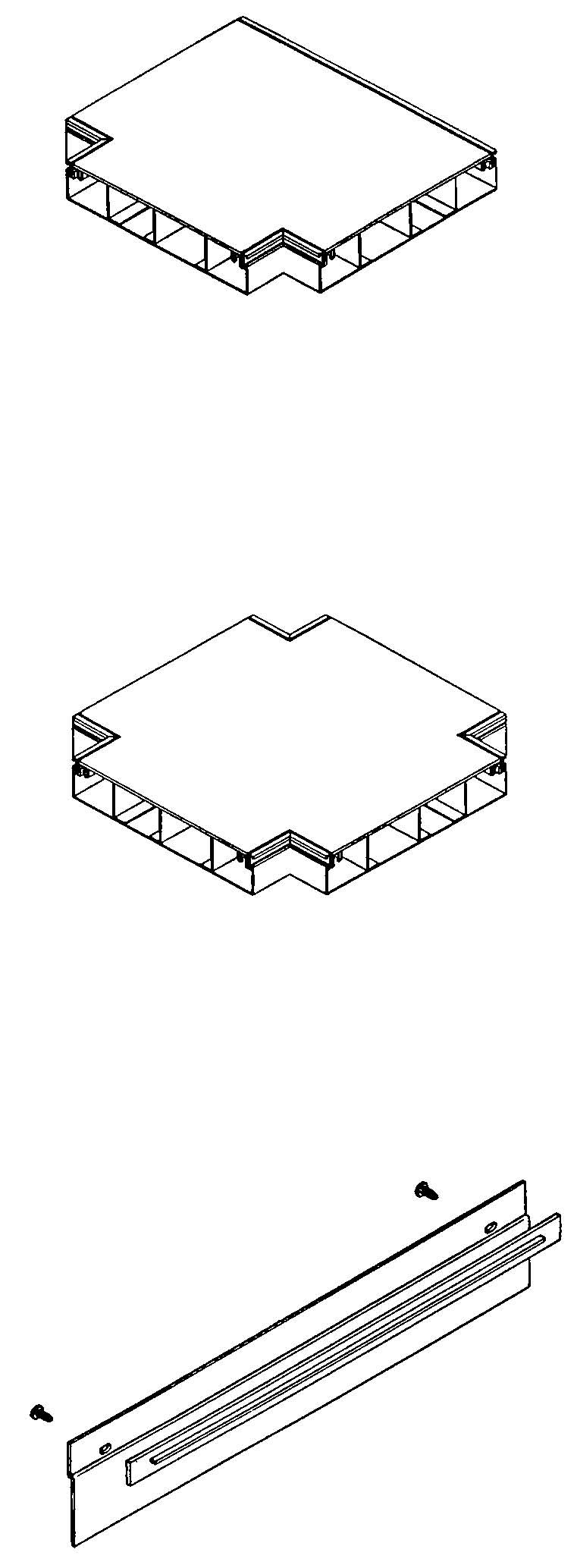
The cover plates for the Raceway Solutions Trench Duct are horizontally adjustable to any point along the duct. The 3/16" thick cover plates come in standard 24" lengths — three are provided per 6' duct section. A 1/4" thick cover plate is also available as a customer option.
A special threaded groove on the track accepts the cover plate screws at any point along the duct, providing the cover unlimited adjustment. This special design relieves the installer from matching the duct frame sections with the covers, eliminating field cutting in most instances. This can substantially reduce installation and maintenance costs.
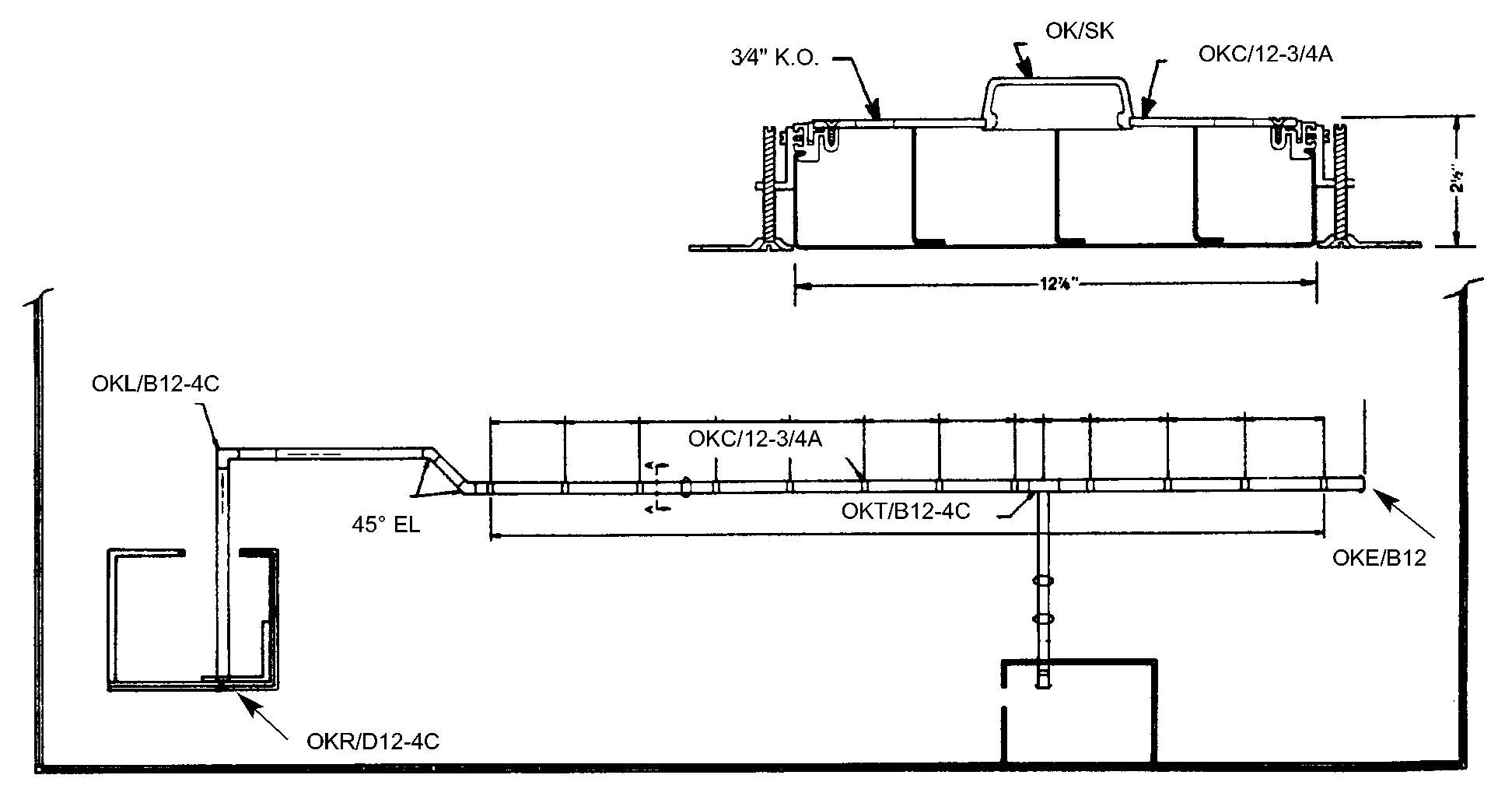
The cable exit may be installed on an exit fitting cover allowing cable to be easily pulled out and activated. The cable exit is reversible to provide accessibility from either direction. The standard cover plates may be removed and exit fitting covers installed for the cable exit.

Raceway SolutionsTM
Trench Duct
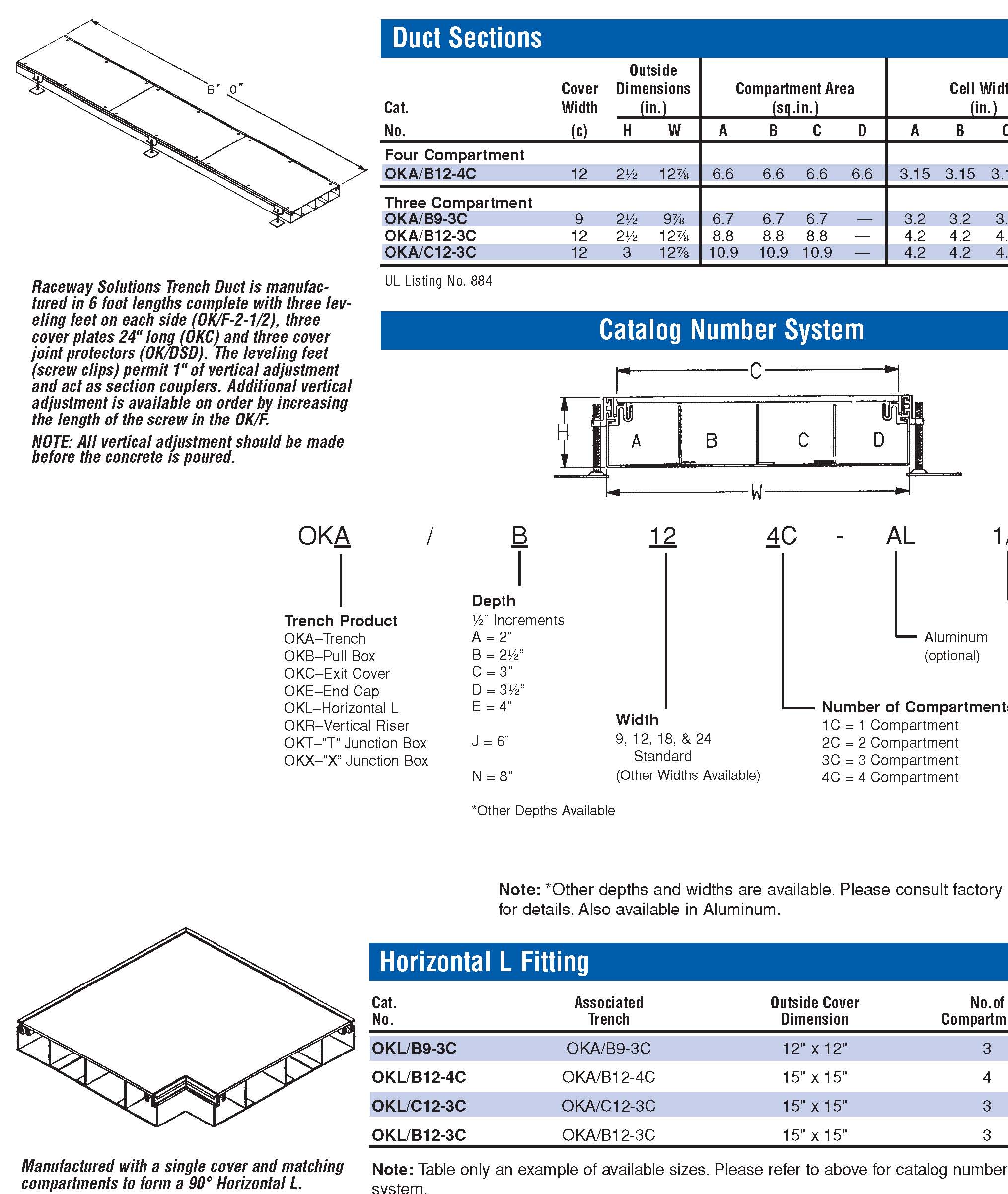
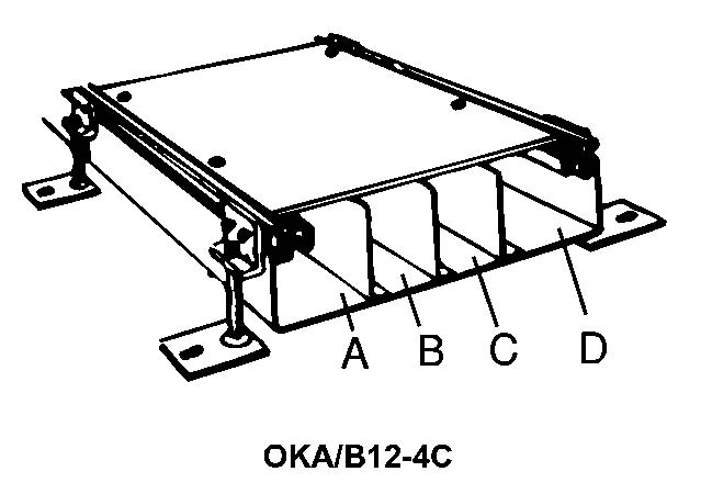
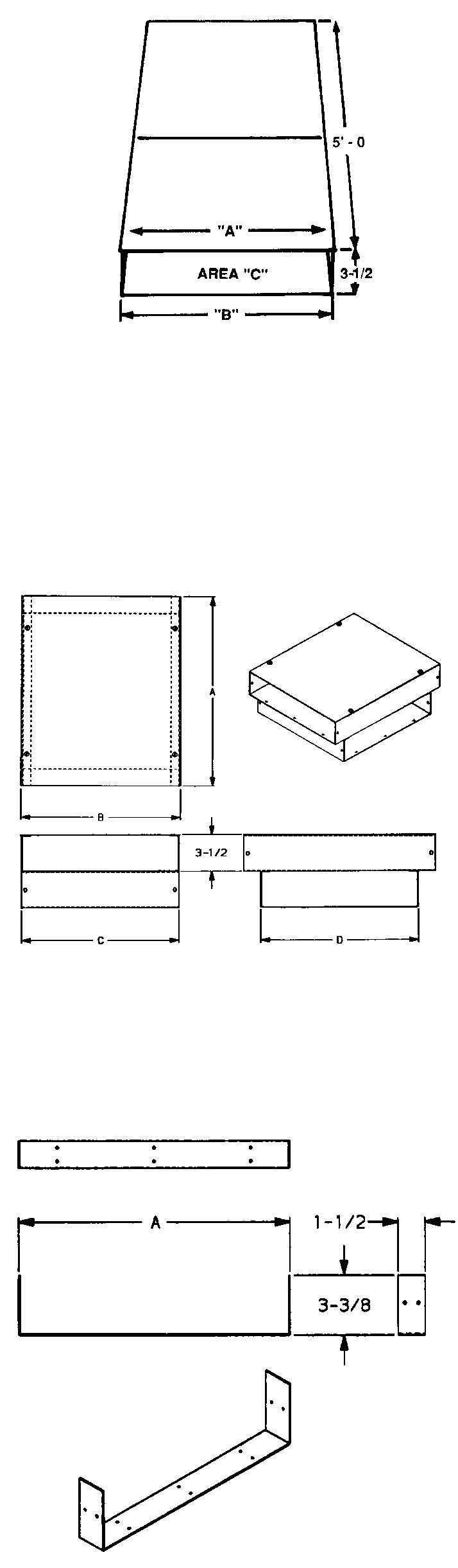
Outside Cover Dimensions
Compartment Area
Cell Width Cat. Width (in.)
(sq.in.)
(in.) No. (c)HW
A B C D A B CD
Four Compartment OKA/B12-4C 12 2½ 12⅞
6.6 6.6 6.6 6.6
3.15 3.15 3.15 3.15
Three Compartment OKA/B9-3C 92½ 9⅞
6.7 6.7 6.7 —
3.2 3.2 3.2 — OKA/B12-3C 12 2½ 12⅞
8.8 8.8 8.8 —
4.2 4.2 4.2 — OKA/C12-3C 12 3 12⅞
10.9 10.9 10.9 — 4.2 4.2 4.2 —
/ B 12 4C -AL 1/4
Note: *Other depths and widths are available. Please consult factory for details. Also available in Aluminum.
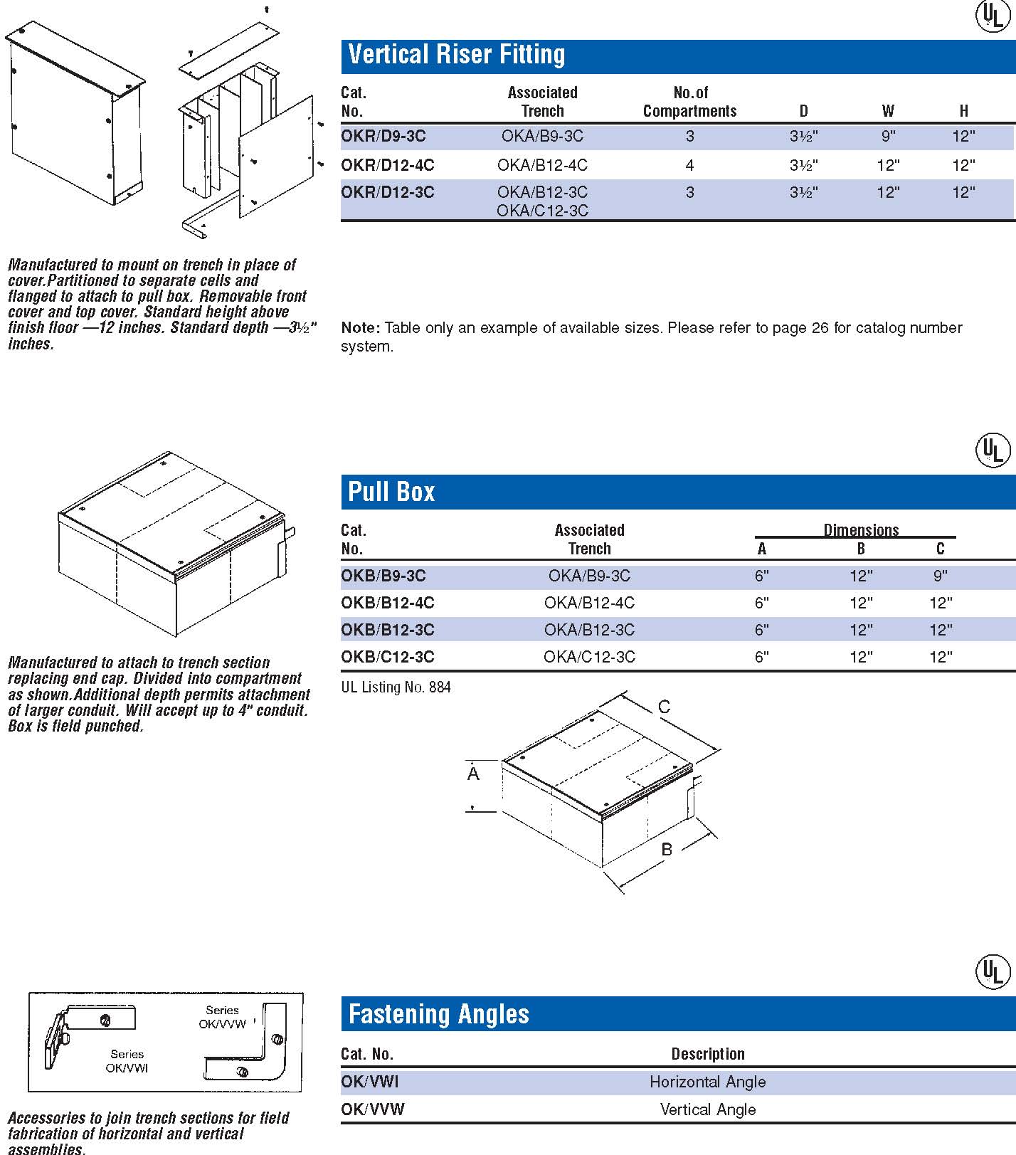
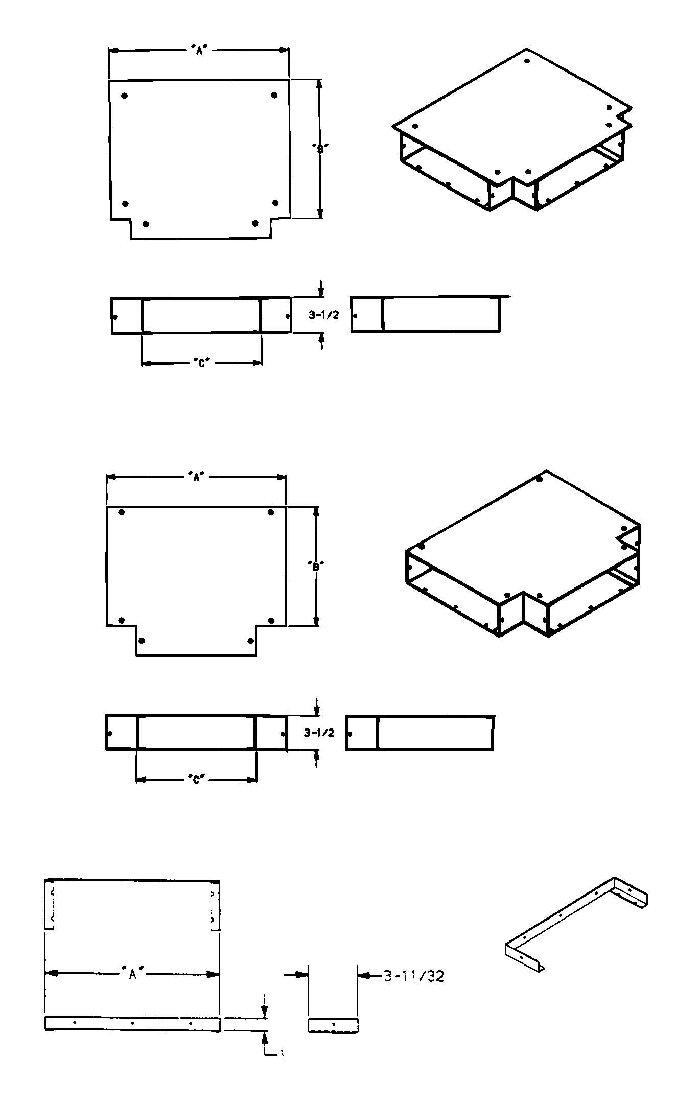
Associated Outside Cover No.of Trench Dimension Compartments
OKL/B9-3C OKA/B9-3C 12" x 12"
3
OKL/B12-4C OKA/B12-4C 15" x 15"
4
OKL/C12-3C OKA/C12-3C 15" x 15"
3
OKL/B12-3C OKA/B12-3C 15" x 15"
3
Manufactured with a single cover and matching compartments to form a 90° Horizontal L.
Depth
½” Increments A = 2” B = 2½” C = 3” D = 3½” E = 4”
Width
9, 12, 18, & 24 Standard N = 8” (Other Widths Available)
J = 6”
*Other Depths Available
¼“ Thick Cover Plate (optional)
Aluminum (optional)
Number of Compartments
1C = 1 Compartment 2C = 2 Compartment 3C = 3 Compartment 4C = 4 Compartment

Raceway SolutionsTM
Trench Duct
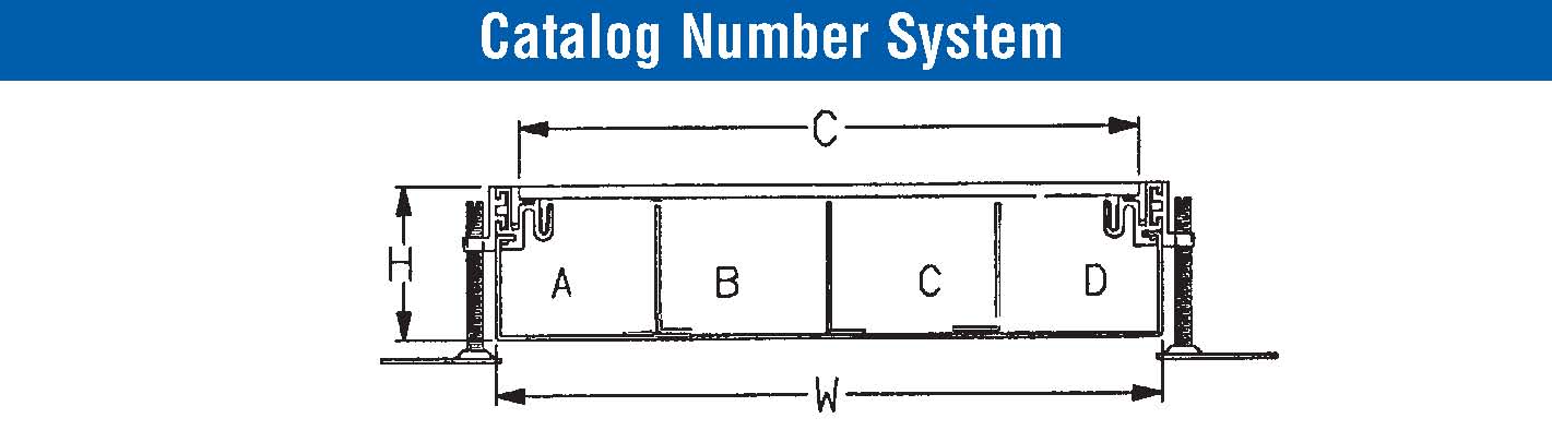
Cat. Cover Associated No. Dimensions Trench
OKT/B9-3C 15" x 12" OKA/B9-3C OKT/B12-4C 18" x 15" OKA/B12-4C OKT/B12-3C 18" x 15" OKA/B12-3C OKT/C12-3C 18" x 15" OKA/C12-3C
Note: Table only an example of available sizes. Please refer to page 26 for catalog number system.
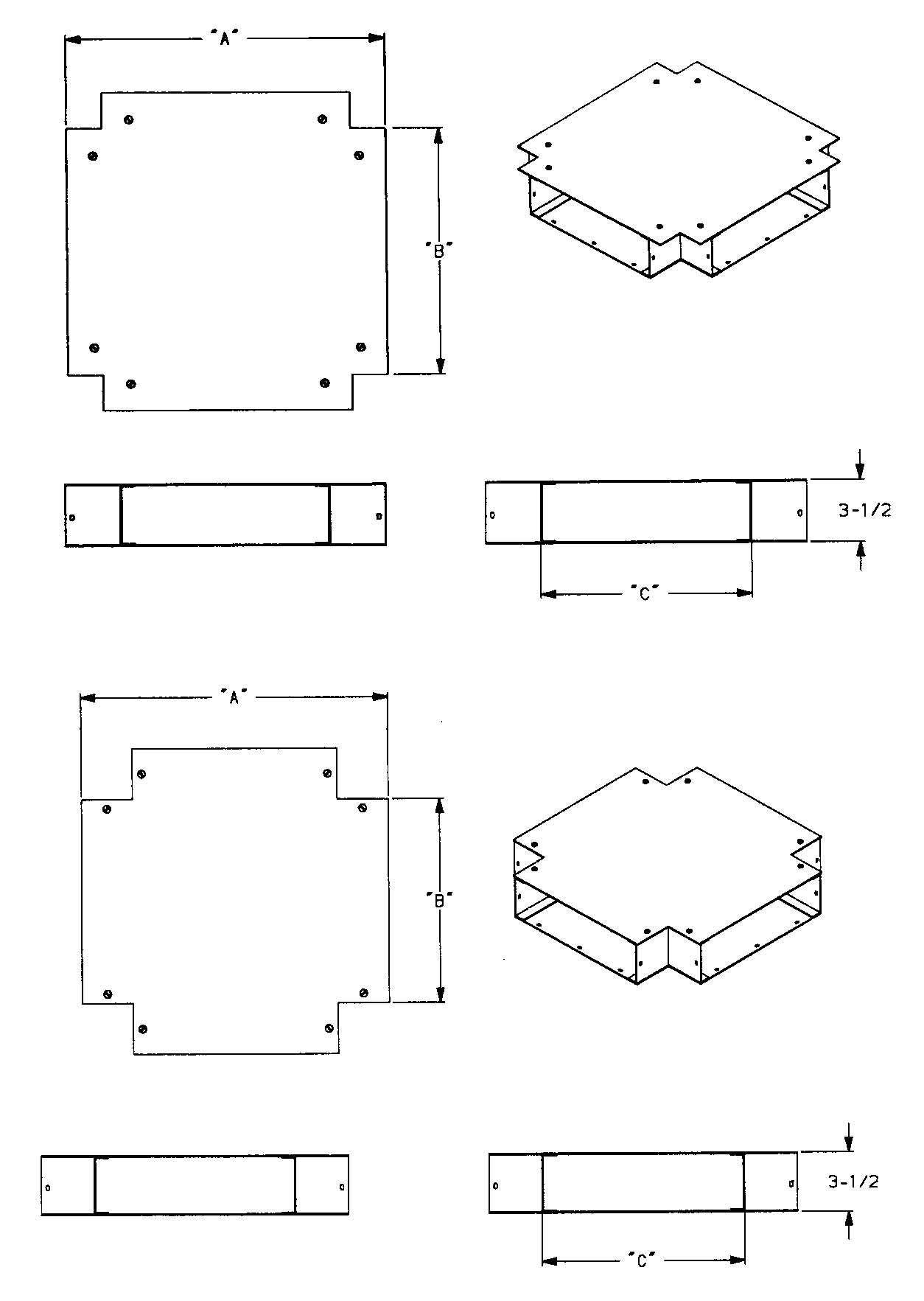
| Cat. | Cover | Associated |
| No. | Dimensions | Trench |
| OKX/B9-3C | 15" x 15" | OKA/B9-3C |
| OKX/B12-4C | 18" x 18" | OKA/B12-4C |
| OKX/B12-3C | 18" x 18" | OKA/B12-3C |
| OKX/C12-3C | 18" x 18" | OKA/C12-3C |
| Cat. | Maximum | ||
|---|---|---|---|
| No. | Width | Conduit | Depth |
| OKE/B9 | 10" | 1¼" | 2⁄" |
| OKE/B12 | 13" | 1¼" | 2⁄" |
| OKE/C12 | 13" | 2" | 3⁄" |

Raceway SolutionsTM
Trench Duct
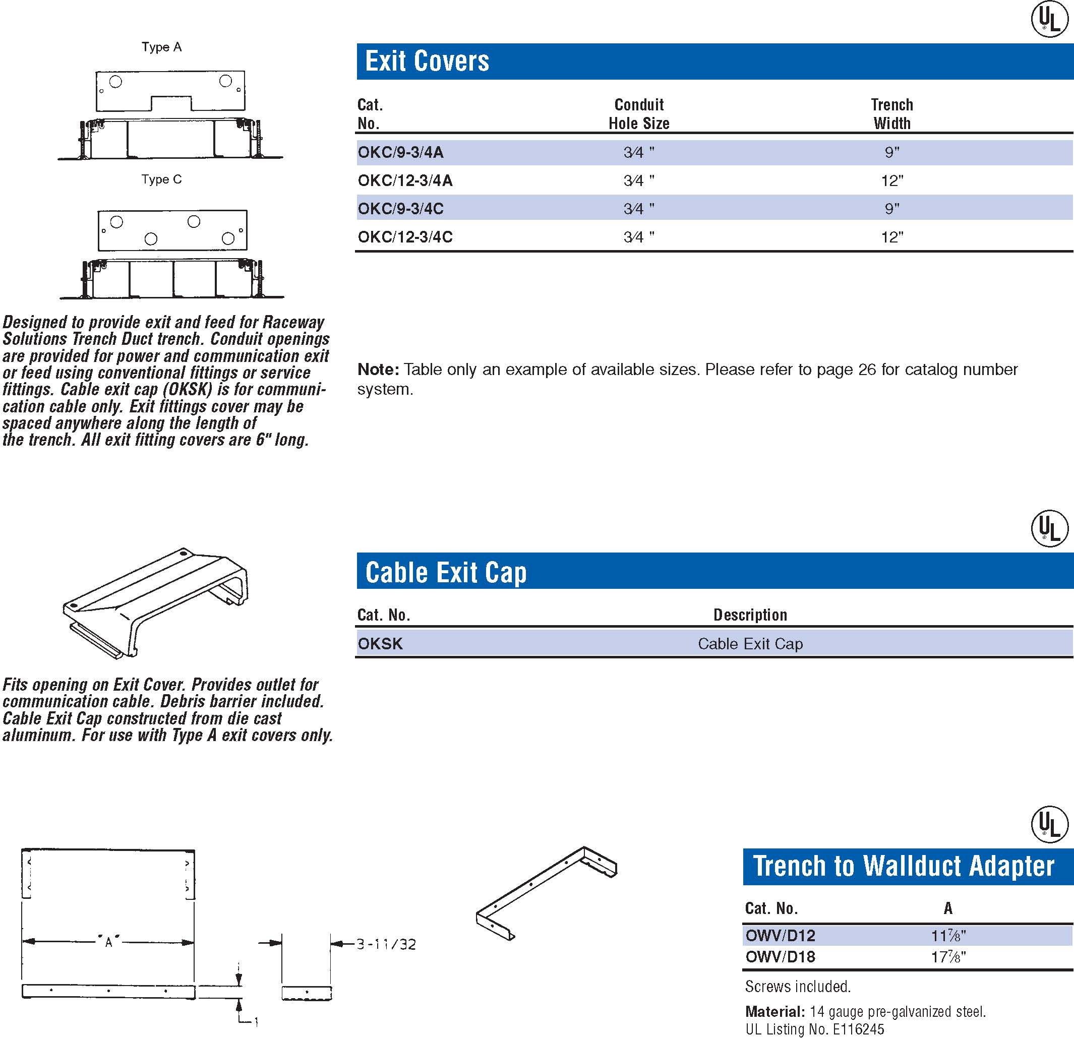
Cat. No. A
OWV/D12 11⁄" OWV/D18 17⁄"
Screws included.
Material: 14 gauge pre-galvanized steel. UL Listing No. E116245

Raceway SolutionsTM
Trench Duct

Raceway SolutionsTM
Trench Duct Specifications
Specifications
Raceway Solution Trench Duct has been designed to offer the most complete in-floor wire management system for computer terminals. The particular use for retail store checkout counters using scanners has been selected for this catalog. Its potential capacity, unlimited point-of-delivery, and wire compartmentalization provide flexibility for current requirements as well as future needs.
Raceway Solution Trench Duct may be specified for stores that are being retrofitted for the use of scanners as well as new stores.
The specifier should consider the following:
1. The two outer compartments for the 12” size (2½" deep) have 6.6 in2 wiring capacity. (This provides greater capacity than 2½" conduit). Two power compartments are offered:
- One for computer dedicated circuits
- One for general purpose power
- The outer compartments should be chosen for the power since runs of conduit can be tapped off the sides of the duct (¾" and 1") to specially placed floor boxes or stubbed out of the concrete to provide power at locations to the left or right of the trench.
- The inside compartments of the four compartment 12" wide duct (OKA/B12-4C) each have 6.6 in2 wiring capacity in a cross-sectional area that is 3.0" x 2¼" on sides. The largest electronic connector can pass through this area and exit with ease. One of these can be designated for
computer cables and the other for intercommunication or telephone. Depending on the sensitivity of the system, these two compartments may be used interchangeably.
- Covers may be adjusted to any location as well as the exit fitting covers. Therefore, predetermination of exit locations is not required and future access to the wiring at any location is available.
- To feed the computer location or checkout counter, service fittings with receptacles may be used or the exit fitting cover hard wired to the point of delivery. For example, flexible metallic conduit or liquidtight conduit may be used between the exit fitting cover and a utility box with a receptacle directly under the counter.
- Cable exit caps may be used for computer, telephone, or intercommunication cables. In certain cases, armored or other approved cable may be permitted with the cable exit cap.

Raceway SolutionsTM
Trench Duct Installation Instructions
A. First raceway. Circuiting within this raceway shall not originate or in any way be connected or routed through dedicated panel.
B Second raceway. All wiring within this raceway is exclusively for the intra-store phone system only.
C. Third raceway. All wiring within this raceway is exclusively for the scanning communication cable.
D. Fourth raceway. All circuiting within this raceway is dedicated for the scanner and must originate from
dedicated panel.
Material
1.1 General inspection of shipment.
1.1.1 Inspect all parts for visible damage.
1.1.2 Determine that the proper number of parts were received. Notify factory immediately if a discrepancy is found.
1.1.3 If shop drawings were provided, installer must familiarize himself with all details.
1.1.3.1 Installer must compare shop drawings with actual jobsite conditions.
1.2 Inspection of Trench Components.
1.2.1 Examine trench for proper number and placement of partitions.
1.2.2 If trench is factory marked, confirm markings.
1.2.3 Do not remove covers from trench. Covers remain on trench during pour.
Before Pour
2.1 General Jobsite Conditions.
2.1.1 Determine a reference point for the start of assembly work. This includes an elevation mark as well as horizontal placement. Confirm by shop drawings when available.
2.1.2 Clear the site of obstructions so installer has a clear working area.
2.1.3 If installation is on grade, prepare the grade and check specifications for type of footing. Note: It is useful to install a rough slab the length of the run. The slab should be 24" wide and poured 2½" to 3½" below the finished floor screed. This will assure fast installation and assure accuracy of positioning.
2.2 Installation Sequence of Trench.
2.2.1 Position trench section being careful of location of the power compartment. (See Store Layout Example above.)
2.2.2 Install and assemble duct to trench if required. (see Part 3.2.6) Refer to installation shop drawings.
2.2.3 Couple trench sections. (See Part 3.2).
2.2.4 Carefully align the trench as shown on the plans.
2.2.5 Fasten the support feet securely to the concrete form, structure or grade.
2.2.6 Install end caps as required.

Raceway SolutionsTM
Trench Duct Installation Instructions
Part 3 —Assembly of Components
3.1 General Assembly Requirements
3.1.1 The power compartment of trench must match and be as shown on the plans.
3.1.2 Continuity of ground must be assured in all metal parts.
3.2 Trench Components.
3.2.1 Do not remove covers before pour.
3.2.2 Trench sections are coupled using coupling clip furnished on the aluminum profile at the end of the trench. Clip may be part of the support assembly.
3.2.3 Check match of internal partition before completing couple.
3.2.4 Set screws on trench coupling clip must be tightened to assure continuity of ground.
3.2.5 If rough slab is not available (see 2.1.3 Note) special care must be taken to assure support of mounting feet and protect against movement during pour.
3.2.6 Junction fittings to adapt trench to underfloor raceway do not require rough slab (see 2.1.3 Note) but must be secure.
3.2.7 Underfloor raceway requires concrete around supports (couplers) and under raceway.
3.2.8 Tape underfloor raceway if ingress of concrete could occur.
3.2.9 Field modification of trench.
3.2.9.1 Where necessary trench can be cut on the jobsite. For this purpose, bandsaws, hacksaws, or cutting wheels can be used.
3.2.9.2 When field cutting, do not remove cover to assure a proper finished joint.
3.2.9.3 Horizontal Ell ’s or offsets may be field fabricated by cutting equal angles from each of the pieces to be joined.
- a.
- 45° cuts from axis of trench join to make a 90° horizontal offset.
- b.
- 22½° cuts join to make a 45° horizontal offset.
- c.
- Partitions must match.
- d.
- Use OK/VWI to join pieces.
3.2.9.4 A vertical Ell may be field fabricated using a section of trench cut to desired height and OK/VVW fastening angles used to join sections.
Part 4 —Securing,Elevating and Leveling System Prior to Pour
4.1 General. The top of the system must be at screed level. Specifically this includes the trench covers.
4.1.1 When elevating and leveling system use laser level, electronic level, transit, conventional level, or any approved system.
4.2 Leveling Trench.
4.2.1 Turn leveling screws of the trench support assembly to bring the cover of the trench to screed.
4.2.2 Level the trench in one direction to prevent distortion of system.
Part 5 —During and After Pour
5.1 General Considerations
5.1.1 Check installation for security, location and elevation. CAUTION: The covers of the system serve as the screed line. They must be protected from accidental movement before and during pour. Correcting components for elevation after concrete has set requires extensive labor.
5.1.2 If concrete mix is especially thin (fluid), gaps and openings in the system should be sealed with duct tape or other approved method.
5.1.3 For aggregate greater than ¼ inch, concrete flow around components must be assured.
5.2 Trench Components.
5.2.1 Covers of trench serve as guide for pouring concrete the level of the finished floor.
5.2.2 Concrete must be inserted under trench by shovel or trowel.
5.2.3 Hand screed to top of trench.
5.2.4 The concrete must adhere tightly to the trench edges.
5.2.5 The covers of the trench must be exposed when the concrete floor is finished.
5.2.6 Remove sufficient covers to allow ventilation after concrete is set.
Part 6 —Activation
6.1 Activation Sequence.
6.1.1 Correct any variation in concrete pour along edges of trench.
6.1.2 Remove covers from trench, and inspect installation.
6.2 Activating Trench.
6.2.1 Upon removing covers 6.1.2, lay the covers beside the trench in their relative position.
6.2.2 Where exit fitting covers or other trench exit fittings are required, lay them beside the trench in their relative position.
6.2.3 If floor finish is not to be interrupted by tile trim to establish continuity of floor cover, tile trim is to remain in shipping position. Do not elevate.
6.2.4 Lay the required wiring in the trench.
6.2.5 Mount the exit fitting covers or other trench exit fittings on trench at proper location.
6.2.6 Install cover joint protectors. OK/DSD.
6.2.7 Install standard covers. Covers may be adjusted or cut if required to complete enclosure.
6.2.8 Remove cover adjacent to exit fittings to complete wiring.
6.2.9 Lay floor covering. Take care to assure level floor over trench. Use floor patch if necessary.
6.2.9.1 If tile trim is used, adhesion between outer tile and tile trim must be assured and tile on covers accurately positioned.

Raceway SolutionsTM
Trench Duct Specifications
Raceway SolutionsTM
Trench Duct Wirefill Capacity
A B C D Total
OKA/B12-4C 6.6 6.6 6.6 6.6 26.4 OKA/B12-3C 8.8 8.8 8.8 — 26.4 OKA/B9-3C 6.7 6.7 6.7 — 20.1
| 3.4 Sq.In.Compartment | ||||||
|---|---|---|---|---|---|---|
| Conductor | RHW/RHH | TW | THW | THWN | XHHW | |
| 14 12 10 8 6 | 41 35 29 16 10 | 100 79 61 28 16 | 66 53 43 22 16 | 156 116 73 36 26 | 103 81 62 29 21 | |
| 5.0 Sq.In.Compartment | ||||||
| Conductor | RHW/RHH | TW | THW | THWN | XHHW | |
| 14 12 10 8 6 | 61 52 43 23 16 | 148 116 90 42 24 | 97 79 64 33 24 | 229 170 108 53 38 | 152 119 92 43 32 | |
| 5.4 Sq.In.Compartment | ||||||
| Conductor | RHW/RHH | TW | THW | THWN | XHHW | |
| 14 12 10 8 6 | 66 56 46 25 17 | 160 125 97 45 26 | 104 85 69 36 26 | 248 184 117 57 41 | 164 129 100 47 34 | |
| 7.8 Sq.In.Compartment | ||||||
| Conductor | RHW/RHH | TW | THW | THHN/THWN | XHHW | |
| 14 12 10 8 6 | 95 81 67 36 25 | 231 181 140 66 38 | 151 123 100 52 38 | 358 266 169 83 60 | 238 186 144 68 49 | |
| 9.2 Sq.In.Compartment | ||||||
| Conductor | RHW/RHH | TW | THW | THHN/THWN | XHHW | |
| 14 12 10 8 6 | 112 95 80 43 29 | 272 213 165 78 44 | 178 146 118 61 44 | 422 314 200 98 70 | 280 220 170 80 58 | |
| 13.7 Sq.In.Compartment | ||||||
| Conductor | RHW/RHH | TW | THW | THHN/THWN | XHHW | |
| 14 12 10 8 6 | 167 142 119 64 44 | 405 318 246 116 66 | 266 217 176 91 66 | 629 468 297 146 105 | 418 328 253 120 87 | |
| 15.7 Sq.In.Compartment | ||||||
| Conductor | RHW/RHH | TW | THW | THHN/THWN | XHHW | |
| 14 12 10 8 6 | 192 163 136 74 50 | 465 365 282 133 76 | 304 249 201 105 76 | 721 536 341 168 121 | 479 376 290 137 100 | |

Raceway SolutionsTM
Wall Duct
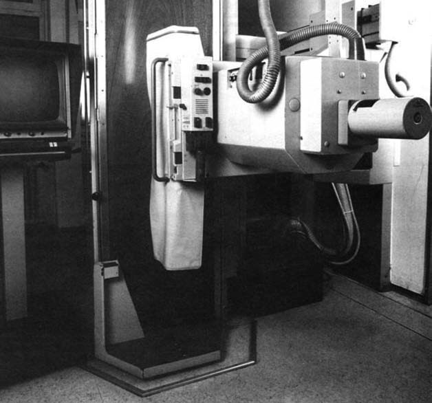
Flush or Surface Mounted Wiring System for X-Ray Rooms
Wall Duct is a steel raceway, approved by U.L. for the enclosure of wiring to X-ray machines in medical applications. The system provides complete lay-in wiring capability in order to accomodate the large cables and connectors used in today’s installations.
Wall Duct, when used in combination with floor trench, provides protection for X-ray room wiring from control consoles to X-ray machines to power supplies to remote locations.
Wall Duct is available in either flush or surface mount and a combination will usually be required on any job. Vertical runs in the walls are usually flush mounted with horizontal runs on walls and all duct in ceiling plenum being surface type.
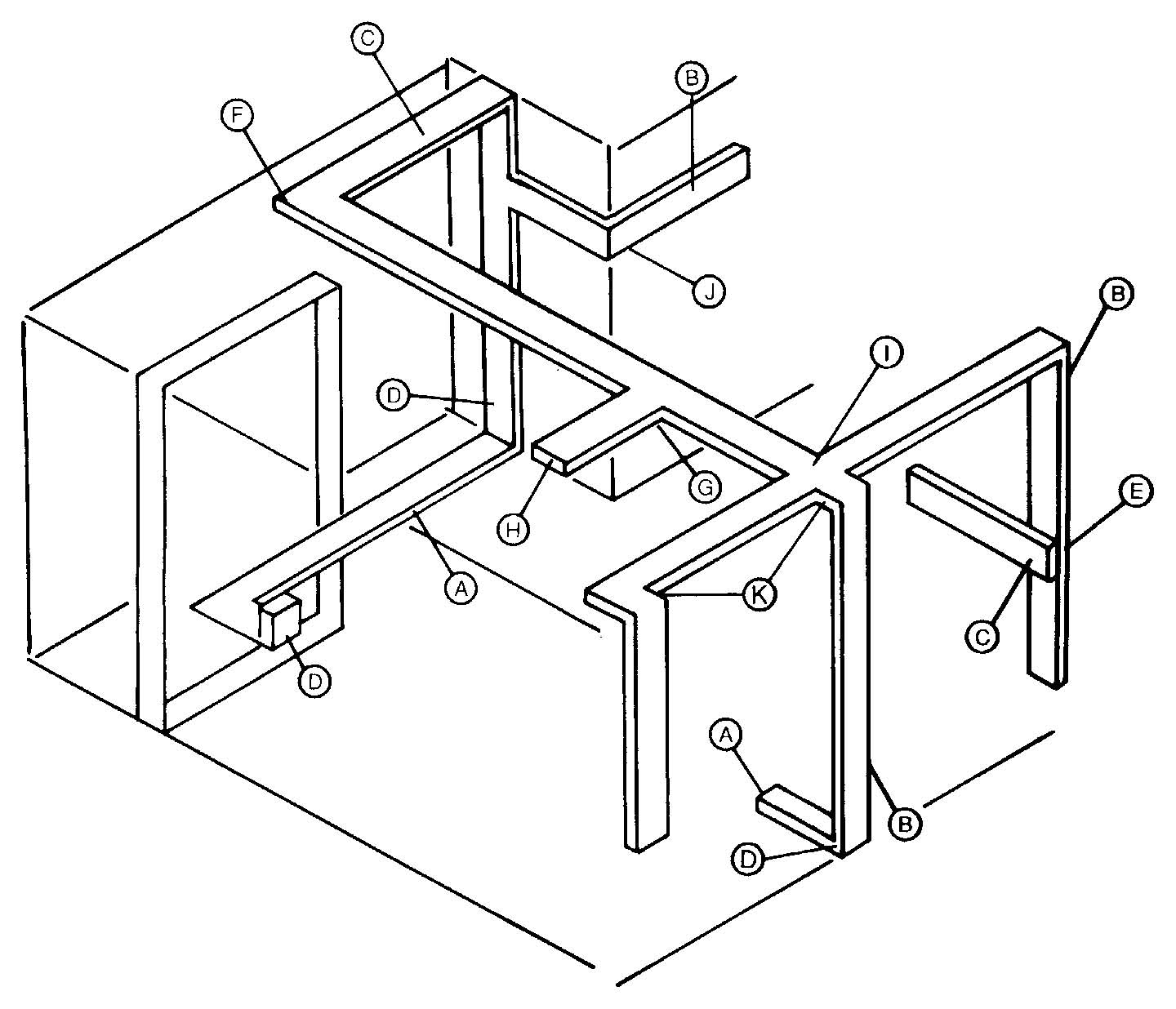
OWA /
Wall Duct Product
OWA–Wall Duct OWB–Adapter OWC–Coupling OWD–Reducer Coupling OWE–End Closure OWF–Cabinet Connector OWH–Horizontal Elbow OWI–Internal Elbow OWL–External Elbow OWP–Partition OWR–Vertical Riser OWT–”T” Unit OWV–Trench to Wall Duct Adapter OWX–”X” Unit
D
Depth
½” Increments A = 2” B = 2½” C = 3” D = 3½” Standard E = 4”
J = 6”
N = 8”
*Other Depths Available
12S AL
Aluminum (optional)
Cover Style
“S”–Surface “F”–Flush
Width
6, 10, 12, & 18 Standard
*Other Widths Available

Raceway SolutionsTM
Wall Duct
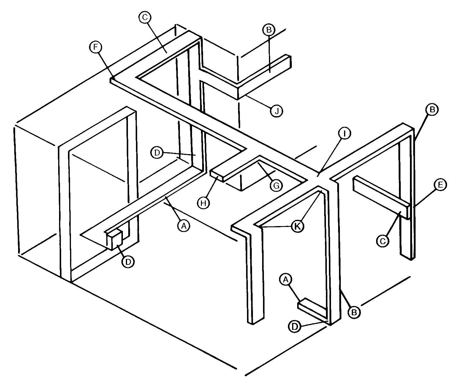
Wall and Ceiling Duct Description
Wall Duct is manufactured of 14 gauge steel. Bodies are pre-galvanized G90-U and covers are dip painted. The covers may be field painted to match room interiors. Straight bodies are 5'0" long with two 30" coverplates. Wall Duct is U.L. Listed under File Number: E116245
A. OKA/B12-3C—Trench 12" wide, 2½" deep, 3 compartment.See page 27.
B. OWA/D12F—Wall Duct -12" wide, 3½" deep, flush mounted. See page
37.
C. OWA/D12S—Wall Duct -12" wide, 3½" deep, surface mounted. See page 37.
D. OWR/D12F—Wall Duct Riser -12" wide, 3½" deep, flush mounted. See page 41.
E. OWB/D12-12—Wall Duct Flush to Surface Adapter -12" wide, 3½" deep flush mounted. See page 37.
F. OWH/D12S—Wall Duct 90° Horizontal Elbow -12" wide, 3½" deep, surface mounted. See page 39.
G. OWT/D12S—Wall Duct “T ” Unit 12" wide, 3½" deep, surface mounted. See page 42.
H. OWE/D12S—Wall Duct End Closure -12" wide, 3½" deep, surface mounted. See page 38.
I. OWX/D12S—Wall Duct “X ” Unit 12" wide, 3½" deep, surface mounted. See page 43.
J. OWL/D12F—Wall Duct External Elbow -12" wide, 3½" deep, flush mounted. See page 40.
K. OWI/D12F—Wall Duct Internal Elbow -12" wide, 3½" deep, flush mounted. See page 39.
L. OWA/D18S—Wall Duct —18" wide, 3½" deep, surface mounted. See page
37.
M. OWA/D18F—Wall Duct —18" wide, 3½" deep, flush mounted. See page
37.

Raceway SolutionsTM
Wall Duct
Cat. “A ” “B ” “C ” No. Cover Width Body Width Area
OWA/D12S 12" 11⁄" 39 sq.in. OWA/D18S 18" ⁄" 59 sq.in.
17OWA/D12F 14" 11⁄" 39 sq.in. OWA/D18F 20" ⁄" 59 sq.in.
17
May be field cut to required length. See installation instructions. Material: 14 gauge pre-galvanized steel. Also available in aluminum. (consult factory) UL Listing No. E116245
Note: Table only an example of available sizes. Other lengths, depths & widths are available. Please refer to page 35 for catalog number system.
Cat. No. A B C D
1111
OWB/D12-12 15" 12" ⁄" ⁄" OWB/D12-18 15" 18" 17⁄" 11⁄"
1117
OWB/D18-12 21" 12" ⁄" ⁄" OWB/D18-18 21" 18" 17⁄" 17⁄"
Includes two couplings. Material: 14 gauge pre-galvanized steel.
UL Listing No. E116245
Cat. No. A
OWC/D12 12"
OWC/D18 18"
Screws included. Material: 14 gauge pre-galvanized steel. UL Listing No. E116245

Raceway SolutionsTM
Wall Duct
Cat. No. Description
OWD/D Reduce from 18" to 12" duct
Screws included. Material: 14 gauge pre-galvanized steel. UL Listing No. E116245
Cat. No. A
OWE/D12F 14"
OWE/D18F 20"
Screws included. Material: 14 gauge pre-galvanized steel. UL Listing No. E116245
Cat. No. A
OWE/D12S 12"
OWE/D18S 18"
Screws included. Material: 14 gauge pre-galvanized steel. UL Listing No. E116245
Cat. No. A
OWF/D12 11⅞"
OWF/D18 17⅞"
Material: 14 gauge pre-galvanized steel. UL Listing No. E116245

Raceway SolutionsTM
Wall Duct
Horizontal Elbow
Cat. No. A B
11OWH/D18F 20" 17⁄"
OWH/D12F 14" ⁄"
Includes one coupling. Material: 14 gauge pre-galvanized steel. UL Listing No. E116245
Horizontal Elbow
Cat. No. A B
OWH/D12S 12" 11⁄" OWH/D18S 18" 17⁄"
Includes one coupling. Material: 14 gauge pre-galvanized steel. UL Listing No. E116245
Cat. No. A B
11OWI/D18F 20" ⁄" OWI/D12F 14" ⁄"
17
Includes one coupling. Material: 14 gauge pre-galvanized steel. UL Listing No. E116245

Raceway SolutionsTM
Wall Duct
Cat. No. A B
OWI/D12S 12" 11⁄" OWI/D18S 18" ⁄"
17
Includes one coupling. Material: 14 gauge pre-galvanized steel. UL Listing No. E116245
Cat. No. A B
11OWL/D18F 20" ⁄" OWL/D12F 14" ⁄"
17
Includes one coupling. Material: 14 gauge pre-galvanized steel. UL Listing No. E116245
Cat. No. A B
OWL/D12S 12" 11⁄" OWL/D18S 18" 17⁄"
Includes one coupling. Material: 14 gauge pre-galvanized steel. UL Listing No. E116245

Raceway SolutionsTM
Wall Duct
Cat. No. Description
OWP/D Internal duct partition
Screws included. Material: 14 gauge pre-galvanized steel. UL Listing No. E116245
Cat.No. A B
11OWR/D18F 20" ⁄" OWR/D12F 14" ⁄"
17
Includes one coupling. Material: 14 gauge pre-galvanized steel. UL Listing No. E116245
Cat. No. A B
OWR/D12S 12" 11⁄" OWR/D18S 18" 17⁄"
Includes one coupling. Material: 14 gauge pre-galvanized steel. UL Listing No. E116245

Raceway SolutionsTM
Wall Duct
Cat. No. A B C
OWT/D12F 18" 14" 11⁄" OWT/D18F 24" 20" ⁄"
17
Includes one coupling. Material: 14 gauge pre-galvanized steel. UL Listing No. E116245
Cat. No. A B C
11OWT/D18S 24" 18" 17⁄"
OWT/D12S 18" 12" ⁄"
Includes one coupling. Material: 14 gauge pre-galvanized steel. UL Listing No. E116245
Cat. No. A
OWV/D12 11⅞" OWV/D18 17⅞"
Screws included. Material: 14 gauge pre-galvanized steel. UL Listing No. E116245

Raceway SolutionsTM
Wall Duct
Cat. No. A B C
OWX/D12F 18" 14" 11⁄" OWX/D18F 24" 20" 17⁄"
Includes two couplings. Material: 14 gauge pre-galvanized steel. UL Listing No. E116245
Cat. No. A B C
OWX/D12S 18" 12" 11⁄" OWX/D18S 24" 18" ⁄"
17
Includes two couplings. Material: 14 gauge pre-galvanized steel. UL Listing No. E116245

Raceway SolutionsTM
Wall Duct Installation Instructions
A. OKA/B12-3C—Trench
B. OWA/D12F—Wall Duct
C. OWA/D12S—Wall Duct
D. OWR/D12F—Wall Duct Riser
E. OWB/D12-12—Wall Duct Flush to Surface Adapter
F. OWH/D12S—Wall Duct 90° Horizontal Elbow
G. OWT/D12S—Wall Duct “T ” Unit
H. OWE/D12S—Wall Duct End Closure
I. OWX/D12S—Wall Duct “X ” Unit
J. OWL/D12F—Wall Duct External Elbow
K. OWI/D12F—Wall Duct Internal Elbow
L. OWA/D18S—Wall Duct
M. OWA/D18F—Wall Duct
Electrical contractor shall review the installation drawings provided and become familiar with all components used. Wall Duct must be installed and used in accordance with National Electrical Code Articles 300 and 660. Derating of power conductors as explained in note 8 of Tables 310-16 and 310-19 of the National Electrical Code shall govern. The maximum wire fill shall not exceed 40% of the interior cross sectional area of the Wall Duct. In all cases, local codes shall govern installation and use of this product.
Wall Duct may be mounted with screws through the sides or back. Screw must be installed so the head of the screw is inside the Wall Duct body. Exposed threads are not permitted on the inside of raceway. Overhead run of Wall Duct may be mounted directly to structural members or hung via trapeze. All hardware for mounting is by others, not Raceway Solutions.
All Wall Duct shall be installed, minus coverplates, before any wiring is placed in any portion of system. Wall Duct and fittings are to be assembled, minus coverplates, using the couplings and screws (8 x ¼ PHST-AB) provided. The screws are to be installed from the inside of the bodies.
When necessary to field cut a straight length to suit conditions, the coupling holes must be field drilled. Use the coupling as a template for proper hole placement. Do not enlarge diameter of coupling holes when field drilling duct body coupling holes.
Pull boxes to be furnished by others.
Field install accessories such as partitions, etc. by match drilling ⁄" diameter holes in the duct body using holes in item as template, and installing self-tapping screws provided with each item.
All above data per NEC, Chapter 9, Table 1.

Raceway SolutionsTM
Wall Duct Wire Fill Capacity
| 39 Sq. In. Compartment | ||||||
|---|---|---|---|---|---|---|
| Conductor | RHW/RHH | TW | THW | THWN | XHHW | |
| 14 | 600 | 1122 | 746 | 1608 | 1122 | |
| 12 | 442 | 862 | 600 | 1173 | 862 | |
| 10 | 357 | 642 | 468 | 739 | 642 | |
| 59 Sq. In. Compartment | ||||||
| Conductor | RHW/RHH | TW | THW | THWN | XHHW | |
| 14 | 908 | 1698 | 1129 | 2433 | 1698 | |
| 12 | 669 | 1304 | 908 | 1774 | 1304 | |
| 10 | 540 | 971 | 709 | 1118 | 971 | |
Number of allowable conductors at 40% fill.

Index
| Catalog Page Number Number | Catalog Page Number Number | Catalog Page Number Number |
|---|---|---|
| 201-1-12 ........................3 | 202-1-24 ........................3 | 203-HB90 ......................7 |
| 201-1-24 ........................3 | 202-15-12 ......................3 | 203-JB-1 ......................5 |
| 201-15-12 ......................3 | 202F-15-12 ....................13 | 203-JB-15 ......................5 |
| 201F-15-12 ....................13 | 202-15-24 ......................3 | 203-JB-2 ........................5 |
| 201-15-24 ......................3 | 202F-15-24 ....................13 | 203-JB-3 ........................5 |
| 201F-15-24 ....................13 | 202-2-12 ........................3 | 203-JB-4 ........................5 |
| 201-2-12 ........................3 | 202F-2-12 ......................13 | 203-UCA ........................6 |
| 201F-2-12 ......................13 | 202-2-24 ........................3 | 203-VEL ........................6 |
| 201-2-24 ........................3 | 202F-2-24 ......................13 | 204-1-12 ........................4 |
| 201F-2-24 ......................13 | 202-3-12 ........................3 | 204-1-24 ........................4 |
| 201-3-12 ........................3 | 202F-3-12 ......................13 | 204-15-12 ......................4 |
| 201F-3-12 ......................13 | 202-3-24 ........................3 | 204-15-24 ......................4 |
| 201-3-24 ........................3 | 202F-3-24 ......................13 | 204-2-12 ........................4 |
| 201F-3-24 ......................13 | 202-B ............................3, 13 | 204-2-24 ........................4 |
| 201-B ............................3, 13 | 202-DCC........................7, 14 | 204-3-12 ........................4 |
| 201-DCC........................7, 14 | 202-DCS ........................5, 14 | 204-3-24 ........................4 |
| 201-DCS ........................5, 14 | 202-ECS ........................6, 14 | 204-B ............................4 |
| 201-ECS ........................6, 14 | 202-HB90 ......................7, 15 | 204-HB90 ......................7 |
| 201-HB90 ......................7, 15 | 202-JB-1 ......................5 | 204-JB-1 ......................5 |
| 201-JB-1 ........................5 | 202-JB-15 ......................5, 13 | 204-JB-15 ......................5 |
| 201-JB-15 ......................5, 13 | 202-JB-2 ........................5, 13 | 204-JB-2 ........................5 |
| 201-JB-2 ........................5, 13 | 202-JB-3 ........................5, 13 | 204-JB-3 ........................5 |
| 201-JB-3 ........................5, 13 | 202-JB-4 ........................5 | 204-JB-4 ........................5 |
| 201-JB-4 ........................5 | DAIFA-2G-3 ..................17 | 204-UCA ........................6 |
| 201-UCA ........................6, 14 | 202-UCA ........................6, 14 | 204-VEL ........................6 |
| 201-VEL ........................6, 15 | 202-VEL ........................6, 15 | CD-3-12 ........................20 |
| 201W-1-12 ....................3 | 202-UCA ........................6, 14 | CD-3-24 ........................20 |
| 201W-1-24 ....................3 | 202-VEL ........................6, 15 | CD-3JF ..........................20 |
| 201W-15-12 ..................3 | 203-1-12 ........................4 | CD-B ..............................20 |
| 201WF-15-12 ................13 | 203-1-24 ........................4 | CD-CC ..........................22 |
| 201W-15-24 ..................3 | 203-15-12 ......................4 | CD-CS ..........................21 |
| 201WF-15-24 ................13 | 203-15-24 ......................4 | CD-CTB ........................20 |
| 201W-2-12 ....................3 | 203-2-12 ........................4 | CD-ES............................21 |
| 201WF-2-12 ..................13 | 203-2-24 ........................4 | CD-HB45L ....................22 |
| 201W-2-24 ....................3 | 203-3-12 ........................4 | CD-HB45R ....................22 |
| 201WF-2-24 ..................13 | 203-3-24 ........................4 | CD-HB90 ......................22 |
| 201W-3-12 ....................3 | 203-B ............................4 | CD-UCA ........................21 |
| 201WF-3-12 ..................13 | 203-DCC........................7, 14 | CD-VEL..........................21 |
| 201W-3-24 ....................3 | 203-DCS ........................5, 14 | CMSF-10 ......................8, 23 |
| 201WF-3-24 ..................13 | 203-ECS ........................6, 14 | DAI-1..............................7 |
| 201W-B..........................3, 13 | 203F-15-12 ....................13 | DAI-2..............................7 |
| 201W-DCC ....................7, 14 | 203F-15-24 ....................13 | DAI-3..............................7, 22 |
| 201W-DCS ....................5, 14 | 203F-2-12 ......................13 | DAI-4..............................7 |
| 201W-ECS ....................6, 14 | 203F-2-24 ......................13 | DAIFA-1G-15 ................17 |
| 201W-HB90 ..................7, 15 | 203F-3-12 ......................13 | DAIFA-1G-2 ..................17 |
| 201W-JB-1 ....................5 | 203F-3-24 ......................13 | DAIFA-1G-3 ..................17 |
| 201W-JB-15 ..................5, 13 | 203F-B ..........................13 | DAIFA-2G-15 ................17 |
| 201W-JB-2 ....................5, 13 | 203F-HB90 ....................15 | DAIFA-2G-2 ..................17 |
| 201W-JB-3 ....................5, 13 | 203F-JB-15 ....................13 | DAIFA-2G-3 ..................17 |
| 201W-JB-4 ....................5 | 203F-JB-2 ......................13 | DAIFA-3G-15 ................17 |
| 201W-UCA ....................6, 14 | 203F-JB-3 ......................13 | DAIFA-3G-2 ..................17 |
| 201W-VEL......................6, 15 | 203F-UCA......................14 | |
| 202-1-12 ........................3 | 203F-VEL ......................15 |

Index
| Catalog Page Number Number | Catalog Page Number Number | Catalog Page Number Number |
|---|---|---|
| DMC-B ..............................7, 22 | JB-CCA-1/2 ........................6, 15 | OWF/D12..........................38 |
| DMC-Z ..............................7, 22 | JB-CCA-1-1/2 ....................6, 15 | OWF/D18..........................38 |
| FACA-1G-AL ....................15 | JB-CCA-2 ..........................6, 15 | OWH/D12F ......................39 |
| FACA-1G-B ......................15 | JB-CCA-3/4 ........................6, 15 | OWH/D12S ......................39 |
| FACA-1G-BGE ..................15 | JB-CCA-B ..........................6, 15 | OWH/D18F ......................39 |
| FACA-1G-BLK ..................15 | OK/VVW ............................29 | OWH/D18S ......................39 |
| FACA-1G-GRY ..................15 | OK/VWI ..............................29 | OWI/D12F ........................39 |
| FACA-2G-AL ....................15 | OKA/B12-3C ......................26 | OWI/D12S ........................40 |
| FACA-2G-B ......................15 | OKA/B12-4C ......................26 | OWI/D18F ........................39 |
| FACA-2G-BGE ..................15 | OKA/B9-3C ........................26 | OWI/D18S ........................40 |
| FACA-2G-BLK ..................15 | OKA/C12-3C ......................26 | OWL/D12F........................40 |
| FACA-2G-GRY ..................15 | OKB/B12-3C ......................29 | OWL/D12S ......................40 |
| FACA-3G-AL ....................15 | OKB/B12-4C ......................29 | OWL/D18F........................40 |
| FACA-3G-B ......................15 | OKB/B9-3C ........................29 | OWL/D18S ......................40 |
| FACA-3G-BGE ..................15 | OKB/C12-3C ......................29 | OWP/D ............................41 |
| FACA-3G-BLK ..................15 | OKC/12-3/4A......................28 | OWR/D12F ......................41 |
| FACA-3G-GRY ..................15 | OKC/12-3/4C......................28 | OWR/D12S ......................41 |
| FAD-CC ............................17 | OKC/9-3/4A........................28 | OWR/D18F ......................41 |
| FAD-MC-B ........................17 | OKC/9-3/4C........................28 | OWR/D18S ......................41 |
| FAD-MC-Z ........................17 | OKE/B12 ............................27 | OWT/D12F ......................42 |
| FA-MCP-1/2-2-B................16 | OKE/B9 ..............................27 | OWT/D12S ......................42 |
| FA-MCP-1/2-AL ................16 | OKE/C12 ............................27 | OWT/D18F ......................42 |
| FA-MCP-1/2-AL ................16 | OKL/B12-3C ......................26 | OWT/D18S ......................42 |
| FA-MCP-1/2-B ..................16 | OKL/B12-4C ......................26 | OWV/D12 ........................28 |
| FA-MCP-1-1/4-AL..............16 | OKL/B9-3C ........................26 | OWV/D12 ........................42 |
| FA-MCP-1-1/4-B................16 | OKL/C12-3C ......................26 | OWV/D18 ........................28 |
| FA-MCP-1-AL ....................16 | OKR/D12-3C ......................29 | OWV/D18 ........................42 |
| FA-MCP-1-B ......................16 | OKR/D12-4C ......................29 | OWX/D12F ......................43 |
| FA-MCP-2-5/8-AL..............16 | OKR/D9-3C ........................29 | OWX/D12S ......................43 |
| FA-MCP-2-5/8-B................16 | OKSK ................................28 | OWX/D18F ......................43 |
| FA-MCP-2-AL ....................16 | OKT/B12-3C ......................27 | OWX/D18S ......................43 |
| FA-MCP-2-B ......................16 | OKT/B12-4C ......................27 | PSF-10 ............................8, 23 |
| FA-MCP-3/4-2-AL..............16 | OKT/B9-3C ........................27 | PSF-10-DR ......................8, 23 |
| FA-MCP-3/4-2-B................16 | OKT/C12-3C ......................27 | PSF-20 ............................8, 23 |
| FA-MCP-3/4-AL ................16 | OKX/B12-3C ......................27 | PSF-20-2DR ....................8, 23 |
| FA-MCP-3/4-B ..................16 | OKX/B12-4C ......................27 | PSF-20-BASE ..................8, 23 |
| FA-MCP-DP-AL ................16 | OKX/B9-3C ........................27 | PSF-20-BLCOV................8, 23 |
| FA-MCP-DP-B ..................16 | OKX/C12-3C ......................27 | PSF-20-BLDVP ................8, 23 |
| FA-MCP-FDP-AL ..............16 | OWA/D12F ........................37 | PSF-20-DUPDVP ............8, 23 |
| FA-MCP-FDP-B ................16 | OWA/D12S ........................37 | PSF-20-DVP139 ..............8, 23 |
| FA-MCP-GFCI-B ..............16 | OWA/D18F ........................37 | PSF-20-DVP160 ..............8, 23 |
| FAPCP-BP-BGE................16 | OWA/D18S ........................37 | PSF-20-TELEDVP............8, 23 |
| FAPCP-BP-BLK ................16 | OWB/D12-12......................37 | PSF-21 ............................8, 23 |
| FAPCP-BP-GRY................16 | OWB/D12-18......................37 | RB-162 ............................7, 22 |
| FAPCP-U-BGE ..................16 | OWB/D18-12......................37 | RB-163 ............................7, 22 |
| FAPCP-U-BLK ..................16 | OWB/D18-18......................37 | |
| FAPCP-U-GRY..................16 | OWC/D12 ..........................37 | |
| FATA-AL ............................16 | OWC/D18 ..........................37 | |
| FATA-B ..............................16 | OWD/D ..............................38 | |
| FATA-BGE ........................16 | OWE/D12F ........................38 | |
| FATA-BLK ..........................16 | OWE/D12S ........................38 | |
| FATA-GRY ........................16 | OWE/D18F ........................38 | |
| JB-CCA-1 ........................6, 15 | OWE/D18S ........................38 |

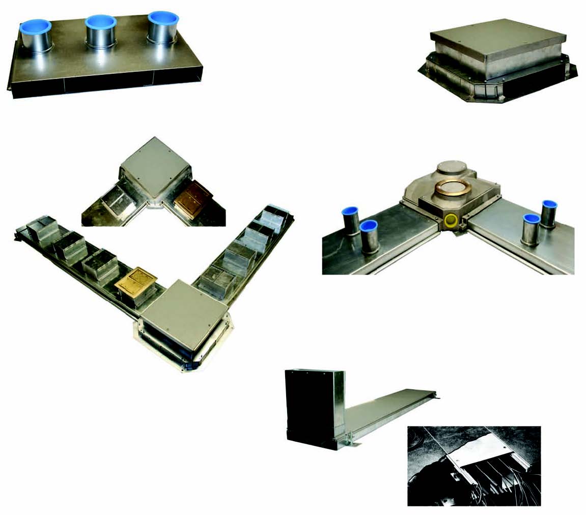
Conventional Underfloor Duct
Casino Duct
Flush Activation Underfloor Duct
Trench and Hospital Wall Duct
Dennis Filges Co. Inc. 238 Center Drive Chicora, PA 16025 Phone 724-287-3735 Fax 724-285-6212 www.filgesco.com Email: info@filgesco.com
